


STUDER Innotec Xtender
Installation and operating Instructions Xtender V1.3 Page 8
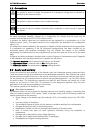
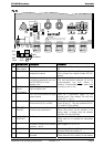
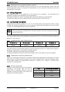
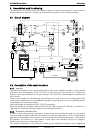
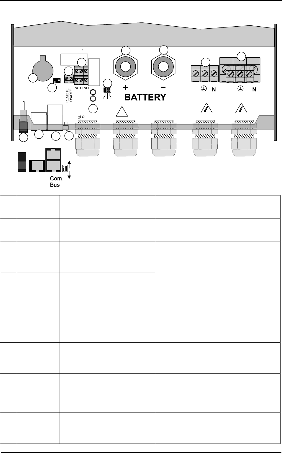
Fig. 4a
A
U
X
I
L
L
A
R
Y
C
O
N
T
A
C
T
L
1
L
2
L
3
A
U
X
1
A
U
X
2
A
C
O
u
t
p
u
t
A
C
I
n
p
u
t
L
L
ON
Open
Terminated
OFF
Temp.
Sens.
1
1
2
A
B
123
2
3
5
6
7
8
9
10
11
12
4
Main
switch
13
14
!
Warning!
Check battery polarity (+/-) before connecting
A wrong connexion may damage the systen
Pos.
Denomination Description Comment
1 ON/OFF
Main switch
Main on/off switch See chapter The real time clock 7.1 - p
24.
2 Temp. Sens Connector for the battery
temperature sensor
See chapter 6.4.2 – p. 24.
Only connect the original Studer BTS-01
sensor
3 Com. Bus Double connector for
connecting peripherals such as
the RCC002/03 or other
Xtender units
4 O / T
(Open /
Terminated)
Switch for terminating the
communication bus.
See chapter 4.5.9 – p. 14.
The two termination switches (4) for the
communication bus both
remain in
position T (terminated) except when both
connectors are in use.
5 -- 3.3 V (CR-2032) lithium ion type
battery socket
Used as a permanent supply for the
internal clock. See chapter The real time
clock 6.2.11 - p 21.
6 -- Jumper for programming the
off/on switch by dry contact
See chapter 6.2.12 – p. 21 and fig. 8b
point (6) and (7). They are positioned at A-
1/2 and B-2/3 by default
7 REMOTE
ON/OFF
Connection terminals for dry
on/off remote connection.
See chapter 6.2.12– p. 21).
When the control via dry contact is not
being used, a bridge must be present
between the two terminals.
8 AUXILIARY
CONTACT
Auxiliary contact (See chapter 6.2.10– p. 21)
Take care not to exceed the admissible
loads
9 -- Activation indicators for auxiliary
contacts 1 and 2
See chapter 6.2.10– p. 21
10 L1/L2/L3 Phase selection jumpers. See chapter 6.3.1. – p.22.
Jumper default at position L1
11 +BAT Positive pole battery connection
terminals
Carefully read chapter 4.5 – p.12
Take care with the polarity of the battery