


STUDER Innotec Xtender
Installation and operating Instructions Xtender V1.3 Page 31
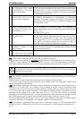
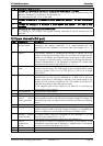
Elem. Description Comment
T Non-secured grid Distribution to users supplied exclusively via the present grid or the
generator.
This distribution is carried out in conformity with the local standards
and regulations.
U Public grid The connection to the public grid imposes adherence to the local
standards and regulations at the responsibility of the installer. The
installation should, in principle, be checked and approved by an
official body.
V Automatic earth-
neutral connection
This connection is deactivated by default. In may be used in certain
specific cases for automatically re-establishing the neutral system
type TT (TNC, TNS, TNC-S) when the Xtender is in inverter mode.
The activation is carried out via RCC-02/03 remote control
configuration {1485}. This operation may only be carried out by
qualified personnel, under the responsibility of these personnel, and in
conformity with the local standards and regulations. See 4.2.3– p.11
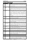
W Galvanic isolator This device (optional) is generally used to reduce the risk of
electrolytic corrosion due to the direct current when a boat is
connected at the dock.
X Source reversing
switch
When the installation has more than one supply source, it is
necessary to install a switching device between the sources,
simultaneously switching the neutral and the phase(s) of these
sources. In all cases this device (manual or automatic) must
guarantee interruption of the connected source before its connection
to another source.
Y Isolation
transformer
This device (optional) prevents the risk of galvanic corrosion due to
direct currents when a boat is connected at the dock.
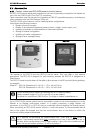
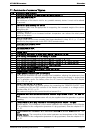
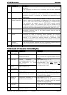
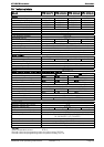
14 Elements of connexion cabinet (Fig 4a)
Pos. Denomination Description Comment
1 ON/OFF
Main switch
Main on/off switch See chapter 7.1 - p 24.
2 Temp. Sens Connector for the battery
temperature sensor
See chapter 6.4.2 – p. 24.
Only connect the original Studer BTS-01
sensor
3 Com. Bus Double connector for
connecting peripherals such as
the RCC002/03 or other
Xtender units
4 O / T
(Open /
Terminated)
Switch for terminating the
communication bus.
See chapter 4.5.9 – p. 14.
The two termination switches (4) for the
communication bus both
remain in
position T (terminated) except when both
connectors are in use.
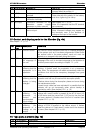
5 -- 3.3 V (CR-2032) lithium ion type
battery socket
Used as a permanent supply for the
internal clock. See chapter 6.2.11 - p 21.
6 -- Jumper for programming the
off/on switch by dry contact
See chapter 6.2.12 – p. 21 and fig. 8b
point (6) and (7). They are positioned at A-
1/2 and B-2/3 by default
7 REMOTE
ON/OFF
Connection terminals for dry
on/off remote connection.
See chapter 6.2.12– p. 21).
When the control via dry contact is not
being used, a bridge must be present
between the two terminals.
8 AUXILIARY
CONTACT
Auxiliary contact (See chapter 6.2.10– p. 21)
Take care not to exceed the admissible
loads
9 -- Activation indicators for auxiliary
contacts 1 and 2
See chapter 6.2.10– p. 21