


3-1
Flue Gas Analysis System Installation 3
TELEDYNE BROWN ENGINEERING
Analytical Instruments
Installation
3.1 Electrical Connections
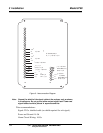
All wiring is to be connected to the barrier type terminal strips on the
back plate assembly within the analyzer. Refer to Figure 6, Interconnection
Diagram, and be certain that the wiring installation complies with the
directions contained in the illustration and in the following discussion.
3.1.1 Power
Refer to the drawings in the supplement at the back of this manual.
All power inputs are fused in order to protect the pump in addition to the
analyzer electronics.
3.1.2 Output Signal Voltage
All models of the analyzer are equipped to provide an output signal
voltage. The magnitude of the signal, which is determined at the time of
purchase, can be preset at the factory to any value between 1 mV and 1 V.
Unless otherwise specified, the outpur will be set to 0–1 VDC.
The output signal, regardless of magnitude, is suitable for high-
impedance devices only (10K Ohms min.).
For interconnection purposes, 22 guage AWG shielded cable conduc-
tor is recommended. Polarize the signal connections as shown in Figure 6
and connect the shield to the analyzer only.