


3-2
3 Installation Model 9700
TELEDYNE BROWN ENGINEERING
Analytical Instruments
`
`
`
`
`
`
1&
&
12
1&
&
12
*1'
1( 87
/,1(
`
`
1&
&
12
6,* 1$/ 287
&2 0 %86 7,%/ (
$1$/ <=( 5
$/ $50
&,5&8,7
&2 0 %86 7,%/ (
$1$/ <=( 5
76
6( 737
6( 737
0$6,* 1 $/ 287
2; <* (1
$1$/ <=( 5
(0)6,* 1$/ 287
$/ $50 &,5&8,7
2; <* (1$1$/ <=( 5
+]
6<67( 0
32 : ( 5,1
76
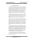
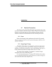
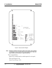
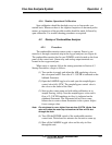
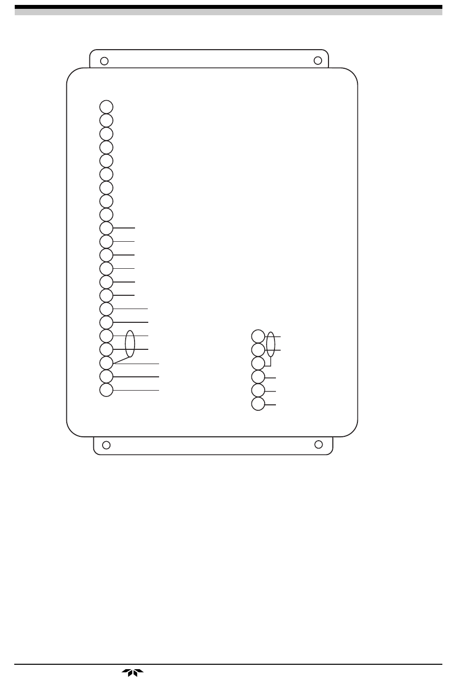
Figure 6: Interconnection Diagram
Note: Ground the shield of the signal cable at the analyzer only as shown
in the diagram. Do not ground either output signal lead. Power and
signal leads should be placed in separate conduits.
Wire recommendations:
Signal: 22 Ga. shielded cable (no shield required for mA signal).
Power and Ground: 16 Ga
Alarm Circuit Wiring: 16 Ga.