


A-11
Flue Gas Analysis System Appendix
TELEDYNE BROWN ENGINEERING
Analytical Instruments
(15) Remove flexible coupling by tapping out the groove pin (8)
and then withdrawing coupling from pump shaft. The shaft (26)
can then be pressed out of the bracket (7) by tapping or pushing
on the coupling end. An arbor press can facilitate this operation.
(16) When the shaft is pressed out it will still be assembled to the
rotor (19), the rotor bearing (20) the bearing guard (23), bearing
guard spacer (22), and retaining ring (3).
(17) Remove plastic plug (16) and retaining ring (18) using a
special pliers which can be obtained from Vanton or a local
industrial distributor. The shaft can then be pressed out of the
rotor.
(18) Remove the bearing guard (23), bearing guard spacer (22), and
bearing retaining ring (3) from the plastic rotor, using special
internal pliers obtained from Vanton or a local industrial
distributor.
(19) Using an
11
/16 " plug, press out outboard bearings (5) and
bearing spacer (6). The pump is now completely disassembled.
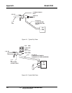
In reassembling the pump, attach the flexible coupling to the shaft,
using the groove pin (8) and then install the bearings (5) and the bearing
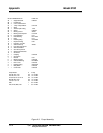
spacer (6) onto the shalt as shown in Figure A-3. Make sure the outermost
outboard bearing rests firmly against the coupling shoulder. This entire
subassembly can then be inserted into the bracket.
The rotor (19) should be completely outfitted with rotor bearing (20),
bearing guard (23), bearing guard spacer (22), and retaining ring (3) prior
to installation onto the shaft, which previously was installed into the
bracket.
The rotor should be installed onto the eccentric portion of the shaft
protruding through the bracket by supporting the entire bracket unit in this
fashion, Insert a
1
/2 " X 5" long rod through the coupling end into the hole
of the shaft. Set the rotor on end, lower the shaft into the rotor and gently
tape the inserted
1
/2 " rod or use an arbor press until the rotor is ‘’home”.
Install rotor bearing ring (18) and replace plastic block with Flex-I-Liner
(16) as previously described. The subassembly can then be bolted to the
motor and while this operation is not particularly critical due to the unique
coupling employed; nonetheless, good practice dictates that the faces of the
bracket and the motor, which are to be bolted together, be clean and free
from burrs.