


www.ti.com
Test Summary
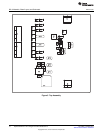
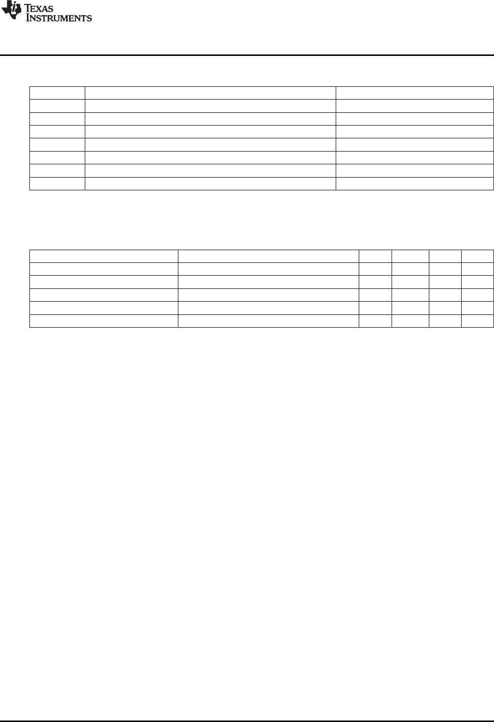
1.4 Controls and Key Parameters Setting
Jack
(1)
Description Factory Setting
JP1 If on, high-side sensing resistor is disabled Jumper on
JP2 Reserved for other ICs Jumper (BATEN, GND) on
JP3 bq24351 GATDRV pin Jumper off
JP4 bq2057C BAT pin connection to bq24351 Jumper on
JP5 bq2057C VCC pin connection to bq24351 Jumper on
JP6 bq2057C CC pin connection to bq24351 Jumper on
JP7 If on, low-side current-sensing resistor is disabled Jumper off
(1)
Short JP1, JP4, JP5, and JP6, and disconnect JP7 to use onboard bq2057C as charger; to use external charger to control
bq24351, disconnect JP1, JP4, JP5, and JP6 and short JP7.
1.5 Recommended Operating Conditions
Symbol Description MIN TYP MAX Unit
Supply voltage, V
IN
Input voltage from ac adapter input 4.5 5 26 V
Battery voltage, V
BAT
Voltage applied at VBAT terminal of J4 0 3–4.2 5 V
Supply current, I
AC
Maximum input current from ac adapter input 0 1.5 A
Charge current, I
chrg
Battery charge current 0.05 0.56 1 A
Operating junction temperature range, T
J
0 125 °C
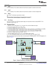
2 Test Summary
2.1 Definitions
This procedure details how to configure the evaluation board. On the test procedure, the following naming
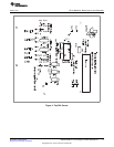
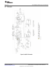
conventions are followed. See the schematic for details.
VXXX External voltage supply name (VIN, VBAT, VOUT)
LOADW External load name (LOADR, LOADI)
V(TPyyy) Voltage at internal test point TPyyy. For example, V(TP1) means the voltage at
TP1.
V(Jxx): Voltage at jack terminal Jxx.
V(TP(XXXXX)) Voltage at test point XXXXX. For example, V(ACDET) means the voltage at the
test point which is marked as ACDET.
V(XXX, YYY) Voltage across points XXX and YYY.
I(JXX(YYY)) Current going out from the YYY terminal of jack XX.
Jxx(BBB) Terminal or pin BBB of jack xx
Jxx ON Internal jumper Jxx terminals are shorted
Jxx OFF Internal jumper Jxx terminals are open
Jxx (-YY-) ON Internal jumper Jxx adjacent terminals marked as YY are shorted
Measure → A,B Check specified parameters A, B. If measured values are not within specified
limits, the unit under test has failed.
Observe → A,B Observe if A, B occur. If they do not occur, the unit under test has failed.
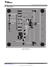
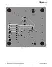
Assembly drawings show locations for jumpers, test points, and individual components.
2.2 Equipment
2.2.1 Power Supplies
Power supply 1 (PS 1): a power supply capable of supplying 15 V at 2 A is required.
3
SLUU455–October 2010 bq24351EVM for Li-Ion Charger Front-End Protection IC
Submit Documentation Feedback
Copyright © 2010, Texas Instruments Incorporated