


FAULT
VBAT
GATDRV
CHGIN
BATEN
OUT
BAT+
GND
HPA666 bq24351EVM
JP7
V
Supply 1
J1
DC+
JP1
U1
J4
BAT+
V
I
2
Ibat
CFET APPLICATION
CIRCUIT
JP6 JP5
JP4
JP3 JP2
U2
J2
J3
I
I
Load
1
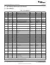
Test Summary
www.ti.com
2.2.2 Load 1
A 10-V (or above), 2-A (or above) electronic load that can operate in constant-current mode.
2.2.3 Load 2
A 10-V (or above), 2-A (or above) electronic load that can operate in constant-voltage mode.
2.2.4 Meters
Four Fluke 75 multimeters (equivalent or better)
Or:
Three equivalent voltage meters and one equivalent current meter
The current meter must be capable of measuring 2-A+ current.
2.2.5 Wire Gauge
All wires connected to the EVM input power supply and output load must be at least AWG 22. The
maximum current is up to 1 A.
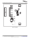
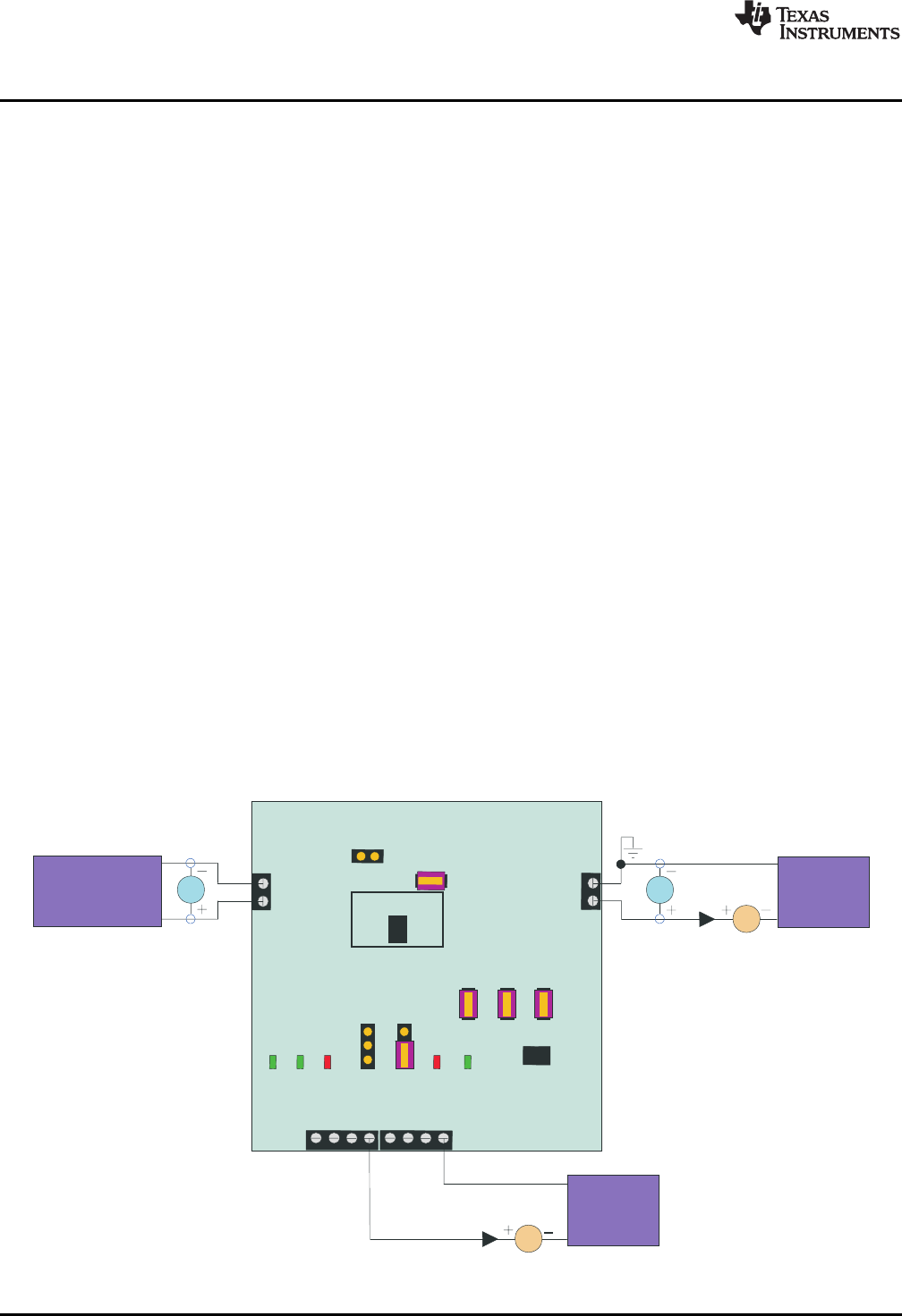
2.3 Equipment Setup
1. Set PS 1 for 0 V ±100 mVdc, 2 ± 0.1 A current limit, and then disable the output.
2. Connect the output of PS 1 to J1 (DC+, DC–).
3. Connect a voltage meter across J1 (DC+, DC–).
4. Connect the output of load 1 in series with a current meter (multimeter) to J2 (CHGIN) and J3 (GND).
Turn on the power of load 1. Set the load current to 1.5 A ±50 mA, but disable the output.
5. Connect the output of load 2 in series with a current meter (multimeter) to J4 (BAT+, BAT–).
6. Connect a voltage meter across J4 (BAT+, BAT–).
7. Set the voltage of load 2 to 3.6 V ±0.1 V, and disable output of load 2.
8. JP1: ON, JP2 (BATEN, GND): ON, JP3: OFF, JP4: ON, JP5: ON, JP6: ON, JP7: OFF.
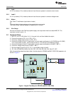
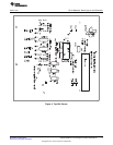
After the preceding steps have been taken, the test setup for HPA666 (bq24351 DSG EVM) appears as is
shown in Figure 1.
Figure 1. Original Test Setup for HPA666 (bq24351 DSG EVM)
4
bq24351EVM for Li-Ion Charger Front-End Protection IC SLUU455–October 2010
Submit Documentation Feedback
Copyright © 2010, Texas Instruments Incorporated