


Background
1-2
1.1 Background
The bq2400x series ICs are advanced Li-Ion linear charge management
devices for highly integrated and space-limited applications. They combine
high-accuracy current and voltage regulation; FET pass-transistor and
reverse-blocking Schottky; battery conditioning, temperature, or input-power
monitoring; charge termination; charge-status indication; and charge timer in
a small, 20-lead TSSOP PowerPAD package.
The bq2400x continuously measures battery temperature using an external
thermistor. For safety reasons, the bq2400x inhibits charge until the battery
temperature is within the user-defined thresholds. Alternatively, the user can
monitor the input voltage to qualify charge. The bq2400x series then charge
the battery in three phases: preconditioning, constant current and constant
voltage. If the battery voltage is below the internal low-voltage threshold, the
bq2400x uses trickle-charge to condition the battery. A preconditioning timer
is provided for additional safety. Following preconditioning, the bq2400x
applies a constant-charge current to the battery. An external sense-resistor
sets the magnitude of the current. The constant-current phase is maintained
until the battery reaches the charge-regulation voltage. The bq2400x then
transitions to the constant voltage phase. The user can configure the device
for cells with either coke or graphite anodes.
Charge is terminated by either of the following methods:
- Maximum time
- Minimum current detection
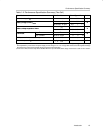
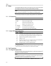
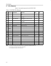
1.2 Performance Specification Summary
This section summarizes the performance specifications of the SLUP051
EVM. Table 1–1 gives the performance specifications of the hubs.
The bq2400x automatically restarts the charge if the battery voltage falls below
an internal recharge threshold.
Table 1–1.Performance Specification Summary (One Cell)
Specification Test Conditions Min Typ Max Units
Input dc voltage, V
DC
4.9 5.0 † V
Battery charge current I
CHG
J4 shorted, J3 open 0.4 0.5 0.6
A
B
attery c
h
arge current,
I
CHG
J3 shorted, J4 open 0.9 1 1.1
A
Battery voltage regulation V
REG
J6 set to V
CC
4.15 4.20 4.25
V
B
attery vo
l
tage regu
l
at
i
on,
V
REG
J6 set to GND 4.05 4.1 4.15
V
Therm fault
High, T
BATMAX
J2 set to Therm 43 48 53
°
C
Th
erm
f
au
l
t
Low, T
BATMIN
J2 set to Therm 0 5 10
°
C
APG (user defined, see data sheet) J2 set to APG ‡
Power dissipation, P
D
(V
I
-V
O
) × I
load
2.3 W
†
V
I
, for a single-cell, should not exceed 5.3 VDC for the 1-A charge rate and 7.6 V for the 0.5-A charge rate. (V
I
is the input voltage
to the bq2400x IC, pins 2 and 3. The power supply source voltage, at J1, is 0.1 V larger than V
I
because of the regulated voltage
drop across the current sense resistor, during constant current regulation.)
‡
If J2 is set to APG, then the chip will be disabled when the input is outside of this range: 4.02 V±0.07 V and 10.76 V ±0.09 V.