


Setup
2-2
2.1 Setup
The bq2400X EVM board requires a DC power source to provide input power
and a single-cell lithium-ion or lithium-polymer battery to charge.
Note:
Other versions of the bq2400x IC can charge two-cell battery packs.
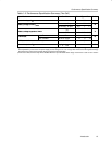
The test setup connections and jumper setting selections are listed below.
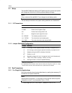
2.1.1 I/O Connections
Jack Connect to:
J1–VCC Power source positive output
J1–GND Power source negative output
J9–+ Positive lead of single lithium cell
J9– – Negative lead of single lithium cell
J9 – VSENSE Tie to battery’s positive terminal
J10 – THERM Tie to thermistor lead in battery pack
J10 – GND
Tie to other thermistor lead (may be GND)
2.1.2 Jumper-Selectable Configuration
Jumper Selection
J3 1-A charge, use two jumpers placed horizontally; no jumpers on J4
J4 0.5-A charge, use two jumpers placed horizontally, no jumpers on J3
J2 Adapter power good (APD) or battery’s thermistor
J5
†
Enable, on or off
J6 Regulation voltage, 4.2 V or 4.1 V (single cell), 8.4 V or 8.2 V (double cell)
J7 Timer, 3-hour (float, no jumper), 4.5-hour, or 6-hour
J8
Stat2 green diode, connect for bq24002/3/5/6/8
‡
†
This jumper enables/disables the IC for bq24001/2/3/4/5/6. For bq24007/8, this jumper enables/
disables the change timer.
‡
For bq24003/6/8 the evaluation board used two LED (red and green) in place of a single
dull-color LED. Therefore, when both LEDs are lit a yellow status is indicated.
2.2 Test Procedures
2.2.1 For Single-Cell Applications
Set up the evaluation board as described above, by making the necessary I/O
connections and jumper selections.
Note:
Before test and evaluation, it is important to verify that the maximum power
dissipation on the IC is not exceeded. Pmax = 2.3 W.
P
diss,
single
cell
= (V
I
– 3 V) × I
CHG
where V
I
= V
CC
–0.1 V