


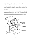
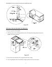
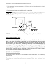
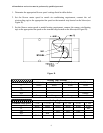
All installations and services must be performed by qualified personnel.
10
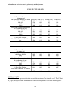
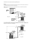
CFM CAPACITY CHARTS
AH1-A
.2 Duct Static Pressure
with heating coil
And applicable Evaporator Coil Model CFM (HI) CFM (M. HI) CFM (M. LOW) CFM (LOW)
1024E and 1030E 1299 1123 992 821
1224-30G1 1756 1202 1073 880
1036E 1435 1231 1055 861
1236G1 1438 1193 1036 860
.2 Duct Static Pressure and applicable
Air Conditioning Coil Only
1024E and 1030E 1390 1243 1085 905
1224-30G1 1591 1335 986 921
1036E 1575 1307 1092 911
1236G1 1523 1280 1074 913
Heating coil
.2 Duct Static Pressure 1514 1261 1055 889
.2 Duct Static Pressure + .3 additional
load 1294 1109 964 785
AH2-A
.2 Duct Static Pressure
with heating coil
And Applicable Evaporator Coil Model CFM (HI) CFM (M. HI) CFM (M. LOW) CFM (LOW)
1060G1 and 1242G1 2052 1632 1326 1034
1042E 1915 1444 1296 1078
1048E 1568 1433 1251 1054
.2 Duct Static Pressure and applicable
Air conditioning coil only
1060G1 and 1242G1 2371 1826 1487 1517
1042E 1794 1580 1377 1132
1048E 1717 1515 1400 1122
Heating coil only
.2 Duct Static Pressure 2161 1685 1330 1047
.2 Duct Static Pressure + .3 additional
load 1977 1459 1200 962
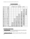
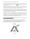
CFM CAPACITY
The CFM at .2 static pressure takes into account the resistance of the internal A-coil. The CFM at
a .5 static pressure accounts for the addition of an external hydronics coil which would typically
add .3 to the static pressure.