


All installations and services must be performed by qualified personnel.
7
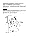
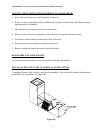
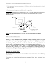
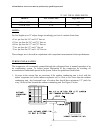
5. Make appropriate hydronic connections to inlet(blower side) and outlet(duct side) of coil and
braze into place.
6. Seal connections through panel with duct sealer or equivalent.
: If drilling or screwing into panel or plate is necessary, make certain drill does not
penetrate into any part of evaporator coil or hot water coil. Personal injury and/or property
damage may result.
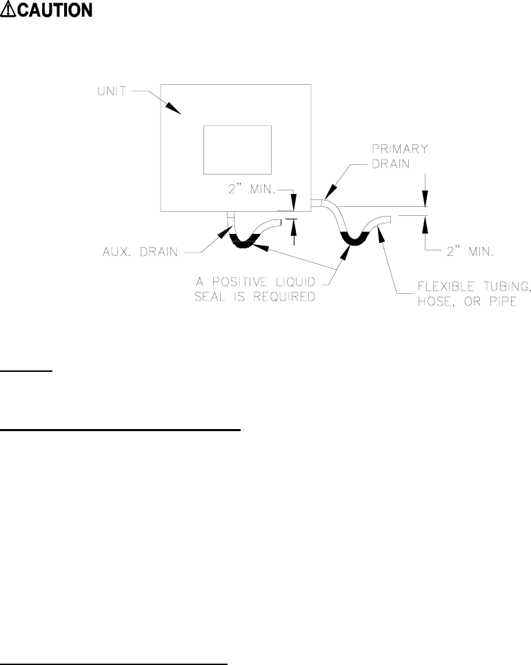
Figure C
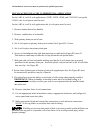
NOTE: Drain lines must be pitched no less than 1/4" per foot away from the air handler.
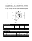
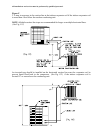
TRIM PANEL INSTRUCTIONS:
Included as a loosely packed part in the condensate drain pan of both air handlers is two trim
panels. These panels are to be used in reducing the free area between both the hydronic coil lines
and the evaporator coil lines. The hydronic coil panel has two holes which the inlet and outlet
lines fit through. This panel is to be secured to the air handler via the prepunched holes and
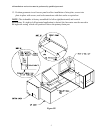
included screws. The evaporator coil panel is a flat rectangular panel measuring 8-1/2” x 3”,
with a 1/2” brake on one edge. The 1/2” brake is to fit into the pocket brake of the side casing
and the larger part of the panel is to be attached to the bottom door via the prepunched holes and
included screws. This panel will close the gap that is created between the side of the air handler,
and the grommet panel that is installed on the evaporator coil.
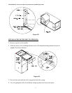
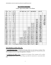
BLOWER AIR ADJUSTMENT
The direct drive blower must be set in order to establish proper air movement. Use the following
steps to do this:
*For cooling only remove low speed connection to terminal block unless continuous fan is
desired.