


iIS-010 series product specification
Ver. B (Oct. 12 200 )
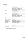
4. Name and Function of Parts
010
POWER LED1 LED2 LED3
RESET
COM0
GPI0
GPI1
GPI2
GPI3
SEL
D.TRIG
TRIG
COM1
GPO0
GPO1
GPO2
GPO3
STR
RDY
CAMERA
ETHERNET
DISPLAY RS232C
POWER
V+
V-
1
5
7
6
2
3 4
8
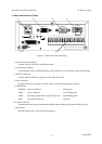
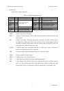
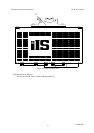
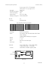
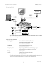
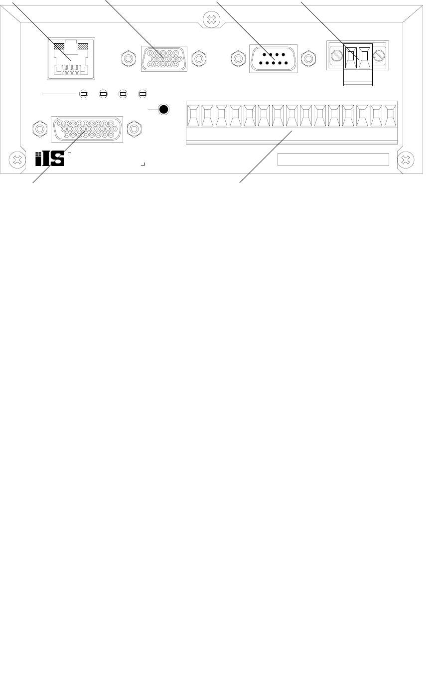
Figure 1. Control unit (Front-panel side)
1. RJ45 connector for Ethernet
Connect with PC or PLC by using Ethernet cable.
2. Local Display connector
A XGA Monitor can be connected directly to the control unit, for local display of the camera image.
3. RS-232C connector
Connect with PC or PLC by using the crossover RS-232C cable.
4. Power connector
Connect the DC Power Supply (+24V DC ±10%) to the control unit power connector.
5. LED indicator
POWER: power-on indicator - steady green
LED1: server “heartbeat” - slow flashing green
LED2: acquisition (frame) done (or processing start) rapid flashing green
LED3: reserved for future use steady off
6. Camera connector
Connect the control unit and camera head with the camera cable provided with iIS-010 series kits.
7. Reset button
Reset the control unit or reset to the factory default.
6
D4130145B