


3
Rack Installation
Read Important Safety Instructions Section Before Installation
Note: The user must determine the fitness of hardware and procedures before mounting. If hardware and procedures are not suitable for the application, contact the manufacturer of the
rack or rack enclosure for assistance. The procedures described in this manual are for common rack and rack enclosure types and may not be appropriate for all applications.
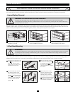
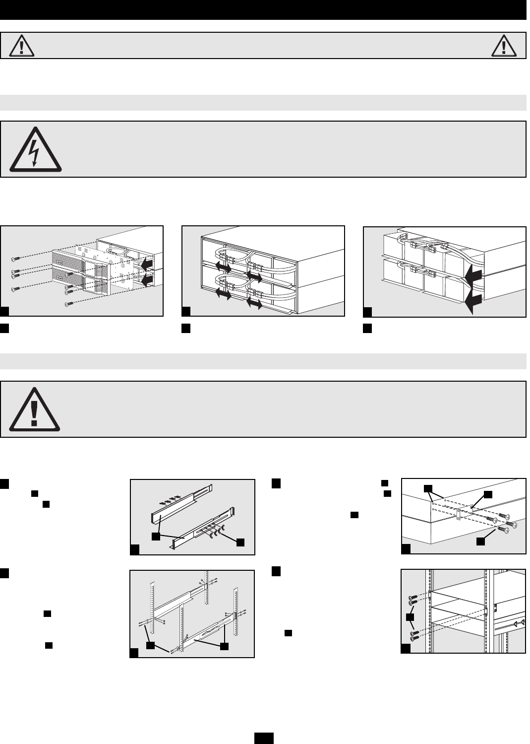
Internal Battery Removal
DANGER! LETHAL HIGH VOLTAGE HAZARD!
Potentially lethal high voltage exists within the battery pack, even when it is not connected to a UPS system. Internal battery
removal/replacement should be performed by qualified electricians or service personnel only, following all local electrical codes and the
precautions listed in this manual.
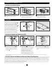
Due to the weight of the 4U external battery pack, Tripp Lite recommends disconnecting and removing the internal batteries from the battery pack prior to rack
installation. After the battery pack has been installed in the rack, the batteries must be reinserted and reconnected before connecting the battery pack to the UPS
system. The battery removal process will be reversed during battery insertion, so taking notes during removal may be helpful.
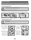
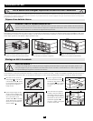
Unscrew and remove Battery Pack Front Panel
and Battery Cover Plate
Disconnect Internal Batteries
(4 Sets of Red/Black Connectors)
Remove Internal Batteries
(Slide From Battery Pack Cabinet)
1
1
2
3
2
3
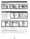
4-Post Rack Mounting
WARNING!
The included mounting shelves will not support more than one battery pack. Do not attempt to stack multiple battery packs on a single set
of mounting shelves. Do not attempt to install the battery pack in a 2-post rack. Failure to follow these warnings will create a risk of
equipment damage and personal injury.
The 4U battery pack includes the hardware needed for mounting in a 4-post rack or rack enclosure, including an adjustable rackmount shelf kit that provides
additional support (required). Note: The 4U battery pack should be mounted below the UPS system power module, as low in the rack as possible.
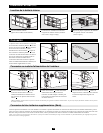
Connect the two segments of each
shelf using the included screws
and nuts . Leave the screws
slightly loose so the shelves can
be adjusted in the next step.
Adjust each shelf to fit the rack,
then mount the shelves in the
lowest available space of the rack
with the screws, nuts and washers
provided . The support ledges
should face inward. Tighten the
screws that connect the shelf
segments .
Attach the mounting brackets
to the forward mounting holes
of the battery pack cabinet with
the screws provided . The
mounting bracket “ears” should
face forward.
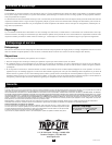
With the help of one or more
assistants, lift the battery pack
cabinet and slide it onto the
mounting shelves. Attach the
battery pack cabinet to the rack by
inserting the appropriate hardware
through the mounting bracket
“ears” and into the rack rails.
H
G
F
E
D
C
B
A
4
5
6
7
4
5
6
7
A
B
C
D
E
F
G
H