


English
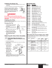
Replacing the T-lip Packings
1. Apply a light coat of household oil to the new lower T-lip
packing and insert it edge-first into the lower end of the
fluid section.
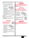
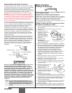
2. Turn the T-lip packing inside the fluid
section cylinder so that the springs of the
T-lip packing face into the cylinder. To do
this, hold the lower edge of the T-lip
packing in place while pressing the upper
edge further into the cylinder.
3. Push the lower T-lip packing as far into
the fluid section as it will go.
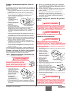
4. Insert the lower spacer into the fluid
section.
5. Apply a light coat of household oil to the
new upper T-lip packing and place it into the upper end of
the fluid section. Position the T-lip packing so that it is
level and the springs of the T-lip packing face into the
cylinder.
6. Thread the packing nut into the fluid section to push the
upper T-lip packing farther into the cylinder, then remove
the packing nut.
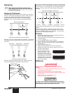
7. Insert the upper
spacer into the fluid
section.
8. Push the upper spacer
as far into the fluid
section as it will go.
9. Screw the packing nut
into the fluid section.
Torque to 25-30 ft./lbs.
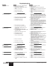
Maintaining the Valves
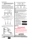
Replacing the Piston and Worn Parts of the Outlet Valve
1. Turn the piston upside down and use a hex wrench to
remove the piston seat retainer from the lower end of the
piston.
2. Cover the open end of the piston and turn the piston right-
side up again to remove the outlet ball seat and outlet ball.
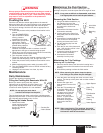
3. Insert a new outlet ball guide into
the new piston. The open end of
the ball guide should face the
open end of the piston. Use the
head of a long nail or screw to
seat the ball guide past the
threads inside the piston if
necessary.
4. Insert a new outlet ball into the
outlet ball guide.
5. Check the outlet ball seat for
wear. If both sides are worn,
insert a new ball seat into the
piston on top of the ball. If only
one side of the ball seat is worn,
insert it into the piston with the
worn side facing away from the
ball.
6. Apply an appropriate thread-locking compound to the
threads of the piston seat retainer.
NOTE: Do not put the new piston into a vise. Putting
the piston into a vise may damage the piston.
Piston
Outlet Ball
Guide
Outlet Ball
Outlet Ball
Seat
Piston Seat
Retainer
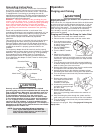
Fluid Section
Cylidner
Upper T-lip Packing
Upper Spacer
Packing Nut
NOTE: For maximum lower T-lip packing life, use a
packing guide tool (see fluid section parts list
for part number) to insert the lower T-lip
packing into the cylinder. If you do not have a
packing guide tool, follow steps 1 – 2 of the
procedure below.
8©SprayTECH. All rights reserved.
7. Screw the piston seat retainer into the lower end of the
piston. Torque the retainer to 12 ft./lbs.
Do not torque the piston seat retainer more than 12 ft./lbs.
Over-torquing may damage the ball guide and prevent
normal operation of the pump.
8. Apply a light coat of household oil to the piston and insert
it, shaft first, into the lower end of the fluid section until it
seats. Tap the bottom of the piston gently with a rubber
mallet if necessary.
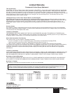
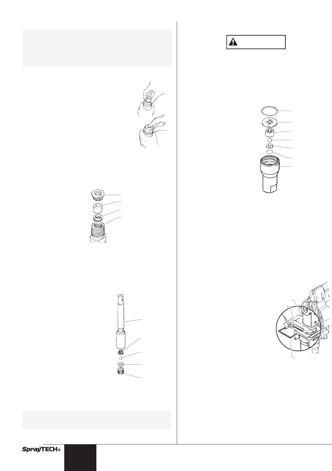
Replacing Worn Parts of the Inlet Valve
1. Remove the O-ring from the inlet valve housing.
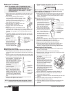
2. Cover the top of the inlet
valve housing and turn it
upside down to remove the
inlet ball stop disk, inlet ball
guide, inlet ball, inlet ball
seat, and inlet ball seal.
3. Insert a new inlet ball seal
into the inlet valve housing.
4. Check the inlet ball seat for
wear. If both sides are
worn, insert a new ball seat
into the housing. If only
one side of the ball seat is
worn, insert it into the
housing with the worn side
facing down.
5. Place a new inlet ball on the inlet ball seat in the housing.
6. Place the inlet ball guide over the inlet ball.
7. Place the inlet ball stop plate over the ball guide.
8. Insert a new O-ring into the inlet valve housing.
9. Place the wrench flats of the inlet valve housing into a
vise and screw the fluid section into the inlet valve
housing. Torque the inlet valve housing to 85-95 ft./lbs.
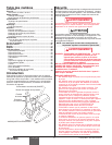
Attaching the Fluid Section
1. Turn the locknut on the fluid section until it reaches the
bottom of the threads.
2. Thread the fluid section into the pump housing.
3. Rotate the fluid section to align the hole in the piston shaft
with the holes in the yoke.
4. Insert the pin through the yoke
and piston.
5. Snap the retaining clip around
the pin and yoke.
6. Screw the fluid section into the
pump housing as far as it will go,
then unscrew it slightly so that
the fluid hose fitting will align
with the fluid hose.
7. Firmly tighten the locknut at the
top of the fluid section assembly
against the pump housing using
an adjustable wrench.
8. Tighten the return line fitting back
to its original position.
9. Fill the reservoirs in the packing nut with hydraulic oil.
10. Replace the pump housing cover and screw in the 6
screws that hold it in place.
11.Tighten the fluid hose onto the fluid hose fitting on the fluid
section.
12. Insert the elbow on the suction set assembly into the
bottom of the inlet valve housing.
13. Push the retaining ring up into the groove inside the inlet
valve housing to secure the suction set assembly in
position.
Yoke
Pin
Retaining Clip
O-Ring
Ball Stop Plate
Inlet Ball Guide
Inlet Ball Seat
Inlet Ball
Inlet Ball Seal
Inlet Valve
Housing
CAUTION