


15
AC 4600 Pro
B_02697
A
H
I
J
K
L
B
C
D
E
F
G
M
N
OPERATING MANUAL
EDITION 06/2012 PART NO. DOC394871
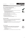
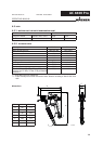
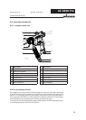
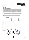
Description
A Suspension hook
B Shaping air regulator
C Spring cover
D Trigger guard
E Trigger safety
F Air connection
G Paint connection
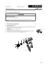
4.4 FUNCTIONAL DESCRIPTION
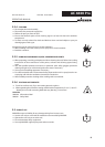
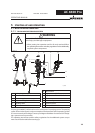
4.4.1 DESIGN OF SPRAY GUN
Description
H Union nut with nozzle guard
I Nozzle / Air cap
J Gun housing
K Filter housing
L Handle tube
M Swivel Air
N Swivel Material
4.4.2 FUNCTIONS OF THE GUN
If the trigger (D) is operated with released locking (E), fi rst the air valve opens. Atomizing
air to fl ow through via air connection (F) to the air cap (I). The material valve opens only if
approx. 1/2 of the trigger guard way are bridged. The quantity of air for the atomization of
the jet spray becomes preset over the external air automatic controller. The atomizing air
control (B) adjusts the total quantity of air fl owing trough the spray gun.
The spray gun is rendered safe with the trigger safety catch (E). Turn the trigger safety catch
in the spraying direction and fasten in the groove.