


23
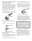
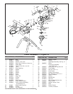
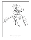
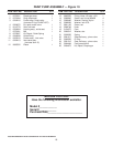
PAINT PUMP ASSEMBLY — Figure 19
ITEM PART NO. DESCRIPTION QTY.
ITEM PART NO. DESCRIPTION QTY.
1 0270201 Diaphragm assy. 1
2 0270494 Ring, diaphragm 1
3 0294216 Pusher assy, outlet valve 1
(Includes O-ring P/N 9971327)
4 0294672 Kit, repair outlet valve 1
5 0010778 Seal, ball seat 1
6 0294264 Housing assy., outlet seat 1
7 0270491 Ball 1
8 0278907 Kit, Repair, Outlet Spring
9 0294508 Outlet fitting 1
10 0253218 Pusher assy., inlet valve 1
11 0294213 Inlet valve assy. 1
(Includes Item 15)
12 9885552 Elbow 1
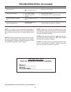
BEFORE YOU CALL
Have the following information available:
Model #____________
Serial #____________
Purchase Date________________________
©1995 WAGNER SPRAY TECH CORPORATION. ALL RIGHTS RESERVED.
13 9885553 Fitting, Hose,1/8 nptm x 3/8 1
14 0089945 Screw, soc hd cap M8x89 4
15 0089482 Washer, Sealing, Nylon 1
16 0088328 Washer, lock 5/16 9
17 9801103 Screw, set 2
18 0288748 Knob 1
19 0154375 Cam 1
20 0090512 Washer, star 1
21 0036352 Spring 1
22 0281317 Stem/ball assy., prime valve 1
23 0090523 O-Ring 1
24 0281316 Seat, ball assy., prime valve 1
25 0294494 Paint pump block 1
26 0294673 Kit, Repair, Diaphragm 1