


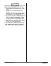

Servicing the Fluid Section
Use the following procedures to service the valves and repack
the fluid section. Perform the following steps before
performing any maintenance on the fluid section.
1. Loosen and remove the four front cover screws. Remove
the front cover.
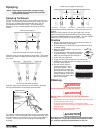
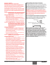
2. Position the slider assembly at the bottom, dead-center of
its stroke so that the connecting pin and retaining ring are
visible below the slider assembly. This is done by turning
the sprayer on and off in short bursts until the connecting
pin is visible below the slider housing.
3. Perform the Pressure Relief Procedure and unplug the
sprayer.
Before proceeding, follow the Pressure Relief Procedure
outlined previously in this manual.
Additionally
, follow all
other warnings to reduce the risk of an injection injury,
injury from moving parts or electric shock. Always
unplug the sprayer before servicing!
4. For Upright Cart units, remove the return hose from the
hose clip on the siphon tube. Unscrew the siphon tube
from the inlet valve housing.
5. For Low Boy cart units, remove the retaining ring from the
bottom of the inlet valve housing using a snap ring pliers.
Remove the return hose clamp and pull the return hose
from its fitting on the pump manifold. Remove the suction
set assembly.
6. Loosen and remove the high-pressure hose from the
outlet fitting on pump manifold.
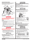
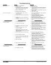
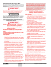
Servicing the Valves
The design of the fluid section
allows access to the inlet valve and
seat as well as the outlet valve and
seat without completely
disassembling the fluid section. It
is possible that the valves may not
seat properly because of debris
stuck in the foot valve seat or outlet
valve seat. Use the following
instructions to clean the valves and
reverse or replace the seats.
1. Using a wrench, loosen and
remove the inlet valve housing
from the pump manifold.
2. Clean out any debris in the
inlet valve housing and
examine the valve housing and
seat. If the seat is damaged,
reverse or replace the seat.
3. Using a 5/16" hex wrench, loosen and remove the outlet
valve retainer from the piston rod.
4. Clean out any debris and
examine the valve housing and
seat. If the seat is damaged, reverse or replace the seat.
5. Remove, clean, and inspect the outlet valve cage and
outlet valve ball. Replace if they are worn or damaged.
6. Reassemble the valves by reversing the steps above.
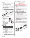
NOTE: Always service the
outlet valve with the
piston rod attached to
the pump. This will
prevent the piston rod
from rotating during
disassembly of the
outlet valve.
Outlet Valve
Retainer
Outlet Valve
Seat
Outlet Valve
Ball
Outlet Valve
Cage
Piston Rod
Inlet Valve
Housing
PTFE
O-Ring
Inlet Valve
Seat
Inlet Valve
Ball
Inlet Valve
Cage
Nylon
Washer
Piston
Bushing
Pump
Manifold
WARNING
10 © SprayTECH. All rights reserved.
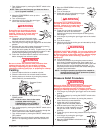
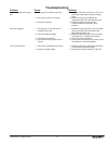
Repacking the Fluid Section
1. Remove the inlet valve assembly using the steps in the
“Servicing the Valves” procedure above.
2. Slide the retaining
ring up on the slider
assembly to expose
the connecting pin.
3. Push the connecting
pin forward through
the slider assembly
and piston. The
connecting pin will
fall into a recessed
area of the gear box
housing where it
can be retrieved.
4. Using 3/8” a hex
wrench, loosen and
remove the two
pump manifold
mounting screws.
5. Pull the pump
manifold down off of
the gear box
housing.
6. Slide the piston rod
out through the
bottom of the pump
manifold.
7. Loosen and remove
the retainer nut and
piston guide from
the pump manifold.
8. Remove the upper
and lower packings
from the pump
manifold.
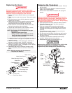
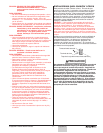
9. Clean the pump manifold and install the new upper and
lower packings. Refer to the illustration below for proper
packing orientation.
10. Inspect the piston rod for wear and replace if necessary.
11. Insert the piston guide into the retainer nut. Thread the
retainer nut into the pump manifold until it is hand tight.
12. Slide the piston guide tool (included in the repacking kit)
over the top of the piston rod and insert the piston rod
through the bottom of the pump manifold. Using a rubber
mallet, tap the bottom of the piston rod lightly until the
piston rod is in position in the pump manifold.
13. Using a wrench, tighten the retainer nut securely.
14. Position the pump block underneath the pump housing
and push up until it rests against the pump housing.
When the connecting pin hole on the piston rod lines up
with the hole in the slider assembly, insert the connecting
pin.
15. Slide the retaining ring down over the connecting pin.
NOTE: Coat the piston guide tool and the piston rod
with grease before inserting them into the
pump manifold.
Install lower packings
with raised lip and O-ring
facing up.
Install upper packing
with raised lip and O-ring
facing down.
O-Ring
O-Ring
Raised Lip
Raised Lip
Slider Assembly
Connecting Pin
Retaining Ring
Retainer Nut
Piston Guide
Upper Packing
Assembly
Pump Manifold
Pump Manifold
Mounting Screw
Piston Rod
Lower Packing
Assembly
Spacer
NOTE: The outlet valve does not need to be
disassembled from the piston rod for this
procedure.