


Always spray at minimum pressure with the gun nozzle tip
removed when using mineral spirits or any other solvent
to clean the sprayer, hose, or gun. Static electricity
buildup may result in a fire or explosion in the presence of
flammable vapors.
1. Follow the “Pressure Relief Procedure” found in the
Operation section of this manual.
2. Remove the gun tip and tip guard and clean with a brush
using the appropriate solvent.
3. Place the siphon tube into a container of the appropriate
solvent. Examples of the appropriate solvent are water for
latex paint or mineral spirits for oil-based paints.
4. Place the return hose into a metal waste container.
5. Set the pressure to minimum by turning the pressure
control knob fully counterclockwise.
6. Move the PRIME/SPRAY valve down to its
PRIME position.
7. Turn on the sprayer by moving the ON/OFF switch to the
ON position.
8. Allow the solvent to circulate through the sprayer and
flush the paint out of the return hose into the metal waste
container.
9. Turn off the sprayer by moving the ON/OFF switch to the
OFF position.
10. Move the PRIME/SPRAY valve up to its
SPRAY position.
11. Turn on the sprayer.
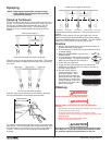
Ground the gun by holding it against
the edge of the metal container while
flushing. Failure to do so may lead to a
static electric discharge, which may
cause a fire.
12. Trigger the gun into the metal waste
container until the paint is flushed out
of the hose and solvent is coming out of the gun.
13.
Continue to trigger the spray gun into the waste container
until the solvent coming out of the gun is clean.
14. Follow the “Pressure Relief Procedure” found in the
Operation section of this manual.
15. Unplug the sprayer and store in a clean, dry area.
Do not store the sprayer under pressure.
Cleaning the Spray Tip
1. Flush the gun with solvent immediately after the work is
completed.
2. Oil the sliding pins to prevent them from seizing up.
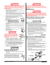
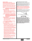
Should the spray tip become clogged, reverse
the spray tip with the lever and pull the trigger.
Once the obstruction comes out of the spray tip,
release the trigger, reverse the spray tip back to
the spray pattern setting, and resume spraying.
CAUTION
NOTE: For long-term or cold weather storage, pump
mineral sprits through the entire system.
WARNING
NOTE: Hold the return hose in the waste
container when moving the
PRIME/SPRAY valve to PRIME in
case the sprayer is pressurized.
WARNING
© SprayTECH. All rights reserved. 7
Do not attempt to clean the tip with your finger.
Do not use a needle or other sharp pointed instrument to
clean the tip. The hard tungsten carbide is brittle and can
be chipped.
Maintenance
Before proceeding, follow the Pressure Relief Procedure
outlined previously in this manual. Additionally, follow all
other warnings to reduce the risk of an injection injury,
injury from moving parts or electric shock. Always unplug
the sprayer before servicing!
General Repair and Service Notes
1. Before repairing any part of the sprayer, read the
instructions carefully, including all warnings.
Never pull on a wire to disconnect it. Pulling on a wire
could loosen the connector from the wire.
2. Test your repair before regular operation of the sprayer to be
sure that the problem is corrected. If the sprayer does not
operate properly
, review the repair procedure to determine if
everything was done correctly. Refer to the Troubleshooting
section to help identify other possible problems.
3. Make sure that the service area is well ventilated in case
solvents are used during cleaning. Always wear
protective eyewear while servicing. Additional protective
equipment may be required depending on the type of
cleaning solvent. Always contact the supplier of solvents
for recommendations.
4. If you have any further questions concerning your
SprayTECH Airless Sprayer, call SprayTECH:
Technical Service...................................1-800-292-4637
Fax ................................................1-800-525-9501
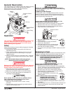
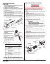
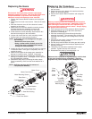
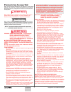
Replacing the PRIME/SPRAY Valve
Perform the following procedure using PRIME/SPRAY valve
replacement kit P/N 0507690.
1. Drive the groove pin out of the valve handle.
2. Remove the valve handle and the cam base.
3. Using a wrench, loosen and remove the valve housing
assembly from the pump manifold.
4. Make sure the gasket is in place and thread the new valve
housing assembly into the pump manifold. Tighten
securely with a wrench.
5. Place the cam base over the valve housing assembly.
Lubricate the cam base with grease and line up the cam
with the pump manifold using the dowel pin.
6. Line up the hole on the valve stem with the hole in the
valve handle.
7. Insert the groove pin into the valve handle and through
the valve stem to secure the valve handle in position.
Dowel Pin
Groove Pin
Valve Stem
Gasket
Pump
Manifold
Valve Housing
Assembly
Valve
Handle
Cam Base
CAUTION
WARNING
WARNING