


Replacing the Gears
Electrostatic discharge (ESD) potential could cause
damage to electronic control. Use SprayTECH ESD wrist
strap P/N 0507958 or equivalent when working on
electronic control with electronic cover removed.
1. Perform the Pressure Relief Procedure and unplug the
sprayer
.
2. Remove the four motor cover screws. Remove the motor
cover.
3. Slide the electronic cover off of the electronic control
assembly on the motor.
4. Remove the four heat sink assembly mounting screws.
Pull back the heat sink assembly to access and
disconnect the two wires coming from the motor.
5. At the electronic control assembly, disconnect the two
black wires coming from the microswitch.
6. Loosen and remove the four motor mounting screws.
7. Pull the motor out of the gear box housing.
8. Inspect the rotor gear on the end of the motor for damage
or excessive wear. If this gear is completely worn out,
replace the motor.
9. Remove and inspect the 2nd stage gear assembly for
damage or excessive wear. Replace, if necessary.
10. Remove and inspect the crankshaft/gear assembly for
damage or excessive wear. If damaged or worn, replace
the crankshaft/gear assembly.
11. Reassemble the pump by reversing the above steps.
During reassembly, make sure the thrust washers is in
place.
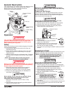
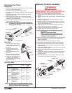
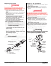
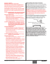
Front Cover
Gear Box Housing
Front Cover Screw
2nd Stage Gear
Thrust Washer
Motor
Crankshaft/Gear
Assembly
Rotor Gear
Motor Mounting Screw
Motor Cover
Motor Cover Screw
NOTE: Refill the gear box with five ounces of
Lubriplate (P/N 9870307).
NOTE: If the motor will not dislodge from the gear
box housing:
• Remove the front cover plate.
• Using a rubber mallet, carefully tap on the
front of the motor crankshaft that extends
through the slider assembly.
WARNING
Replacing the Transducer
1. Loosen and remove the four front cover screws. Remove
the front cover.
2. Stop the sprayer at the bottom of its stroke so that the
piston is in its lowest position.
3. Perform the Pressure Relief Procedure and unplug the
sprayer.
Before proceeding, follow the Pressure Relief Procedure
outlined previously in this manual.
Additionally, follow all
other warnings to reduce the risk of an injection injury,
injury from moving parts or electric shock. Always unplug
the sprayer before servicing!
4. Tilt the sprayer back for easy access to the fluid section.
5.
Slide the retaining ring up on the slider assembly to
expose the connecting pin.
6. Push the connecting pin forward through the slider
assembly and piston. The connecting pin will fall into a
recessed area of the gear box housing where it can be
retrieved.
7. Using 3/8” a hex wrench, loosen and remove the two
pump manifold mounting screws.
8. Pull the pump manifold down off of the gear box housing.
9. Using a wrench, remove the transducer assembly from
the pump manifold.
10. Thread the new transducer assembly into the pump
manifold. Tighten securely with a wrench.
11. Reassemble the pump by reversing steps 1–8.
Make sure the transducer is aligned properly with the hole
in the pump manifold during reassembly. Improper
alignment may cause damage to the transducer o-ring.
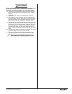
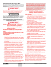
Gear Box
Housing
Slider
Assembly
Pump
Manifold
Pump
Manifold
Mounting
Screw
Front
Cover
Front
Cover
Screw
Transducer
Assembly
Connecting Pin
Retaining Ring
CAUTION
WARNING
© SprayTECH. All rights reserved. 9