


15
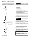
Repacking Fluid Section
Continued from Page 14
(Refer to Figure 14, Page 14)
16. Remove lower O-Ring (27) from inlet valve holder.
17. Place cylinder (8) in vise (on wrench flats) and
tighten.
18. Remove packing nut (1).
19. Gently hammer piston assembly down with rubber
mallet. Piston assembly will come out.
20. Remove lower packings (12, 13) and lower female
adapter (14) if they have not already fallen out.
21. Remove lower male adapter (11) and wave spring (9).
22. Remove upper packings (3, 4 ) and adapter (2, 5) and
wave spring (6).
23. Insert connecting pin through hole in piston rod (10).
Lock connecting pin in vise jaws so piston rod is
vertical. DO NOT put piston rod itself in vise. The vise
jaws will damage piston rod.
24. Remove jam nut (21).
25. Remove piston seat retainer (20) with 5/16'' allen
wrench.
26. Remove piston rod assembly from vise.
27. Remove washer (19), ball seat (18), ball (17), ball
cage(16) and ball stop disc (15) from lower end of
piston rod assembly.
28. Inspect ball, and ball seat for damage. If the seat is
worn or damaged it can be flipped to the un-used side.
Ball must be replaced if damaged or the seat is flipped.
Washer must be replaced.
29. Hold piston assembly in vice using same procedure as
step 23.
30. Insert upper ball stop disc (15), ball cage (16), ball (17),
ball seat (18), and washer (19) into piston assembly.
31. Put removable loctite on piston seat retainer (20).
Insert into piston assembly and tighten. Torque to 250
in./lbs.
32. Put removable loctite on jam nut (21). Tighten onto
piston seat retainer. Torque to 200 in./lbs. Remove
piston assembly from vice.
33. Place cylinder in vice using wrench flats and tighten.
34. Soak new leather packings in linseed oil for 5 minutes.
Do not oversoak.
35. Insert wave spring (9) and lower male adapter (11) into
cylinder. Remove leather packings from oil. Install
leather packings (13) alternatively with UHMWPE
packings (12). Insert lower female adapter (14).
36. Insert piston assembly into bottom of cylinder (8). A
slight force may be required to push piston rod through
packings.
37. Place O-Ring (27), lower ball seat (26), ball cage (25),
ball (24) and lower ball stop disc (23) into inlet valve
holder (28).
38. Put anti-seize compound on lower threads of cylinder
(8). Put O-Ring (22) on cylinder. Loosen vise and tilt
cylinder assembly at about a 45 degree angle. Tighten
vise again.
39. Tighten foot valve holder assembly onto cylinder with
an appropriate adjustable wrench until cylinder bottoms
out in foot valve holder. Make sure to use wrench flats
on foot valve holder to tighten completely. Torque to 40
ft./lbs.
40. Soak remaining new leather packings in linseed oil for
5 minutes. Do not oversoak.
41. Insert wave spring (6), upper male adapter (5). Remove
leather packings from oil. Install leather packings (4)
alternatively with UHMWPE packings (3). A tool, Wagner
part #06009, may be required to compress packings
down. Insert female adapter (2).
42. Install packing nut (1) and tighten until the nut bottoms
out in cylinder. Torque to 25 ft./lbs. Do not over-
tighten.
43. Install large locknut (7) onto upper cylinder (8) and
turn until nut bottoms out on threaded section of
cylinder.
44. Put anti-seize compound on upper cylinder threads.
45. Remove fluid section from vice and install into main
pump housing. Piston rod (10) will align itself inside
yoke.
46. Rotate fluid section slightly to align hole in yoke and
hole in piston assembly. Insert connecting pin.
Replace spring retainer.
47. Thread fluid section into pump housing completely,
then unscrew up to 3/4 turn to align outlet elbow with
fluid hose.
48. Rotate large locknut (7) clockwise until tight against
drive housing.
CAUTION
Do not over tighten or damage to
cylinder may occur.
CAUTION
Hold hand under piston rod (10).
Damage can occur if piston rod
falls to the floor. Lower packings may also fall out.