


10
Replacement of Drive Belt
WARNING: MAKE SURE TO DISCONNECT
ELECTRICAL POWER TO THE DRILL PRESS TO
AVOID THE POSSIBILITY OF INADVERTENT
OPERATION AND EXPOSURE TO POTENTIALLY
LETHAL VOLTAGE LEVELS.
Manual Speed Control -
Models 2221VS and 2223VS
1. Start drill press. Set speed control to highest
speed. Stop drill press.
2. Disconnect electrical power by setting drill press
circuit breaker to OFF.
3. Remove head cover.
4. Remove belt. (With speed control setting at the
highest speed, the belt should be loose enough to
remove.)
5. Install the replacement belt. Install the head
cover.
6. Set the drill press circuit breaker ON.
7. Operate the drill press to verify correct operation.
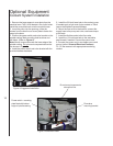
Inverter Speed Control -
Models 2232AC and 2234AC
1. Disconnect electrical power by setting drill press
circuit breaker to OFF.
2. Remove pan screws from small cover (around
column). Remove pan screws and eight bolts
from head cover.
3. Loosen set screw and remove shift lever.
4. Remove plastic spindle cup.
5. Remove head cover. Leave small cover in place.
6. Disconnect electrical wiring from motor junction
box. Remove motor from mounting plate.
7. Remove motor mounting plate.
6. Remove three screws from pulley covers (discs).
Remove used belt. Install the replacement belt.
8. Install pulley covers and secure with three screws
in each pulley cover.
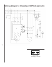
9. Install motor mounting plate. Install motor and.
connect electrical wiring (refer to Wiring
Diagram section for wiring details).
10. Install the head cover and secure with pan
screws and eight bolts.
11. Secure small head cover to head cover using pan
screws.
12. Set the drill press circuit breaker ON.
13. Operate the drill press to verify correct operation.
Replacement of Motor
WARNING: MAKE SURE TO DISCONNECT
ELECTRICAL POWER TO THE DRILL PRESS TO
AVOID THE POSSIBILITY OF INADVERTENT
OPERATION AND EXPOSURE TO POTENTIALLY
LETHAL VOLTAGE LEVELS.
Manual Speed Control -
Models 2221VS and 2223VS
1. Remove drive belt (refer to Replacement Of
Drive Belt).
2. Disconnect electrical wiring from motor junction
box.
3. Remove nuts from mounting studs securing
motor to drill head. Remove motor.
4. Remove upper and lower pulleys and related
components from motor shaft.
5. Install upper and lower pulleys and related
components on replacement motor shaft.
6. Install motor on mounting studs and secure with
nuts.
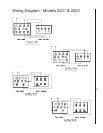
7. Connect electrical wiring (refer to Wiring
Diagram section for wiring details).
8. Install drive belt (refer to Replacement Of Drive
Belt).
9. Operate drill press to verify proper operation.
Inverter Speed Control -
Models 2232AC and 2234AC
Refer to Replacement Of Drive Belt for instructions
for removal of the drive motor.
Lubrication
Following are lubrication recommendations for drill
press components.
Manual Speed Control -
Models 2221VS and 2223VS
1. Spindle pulley drive: Lubricate spindle splines
occasionally with light grease.
2. Quill and column: Lubricate with light film of
oil.
3. Lift rack: Lubricate regularly with SAE 20 oil
(clean rack with kerosene before applying oil).
4. Variable drive:
a. Speed control fork: service oil hole with
SAE 20 oil once a week.
b. Countershaft spindle and push rod:
lubricate with SAE 20 oil occasionally.
c. Speed control handle cam: clean and
grease with medium cup grease annually.
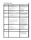
Maintenance