


8
Raising the Drill Head and
Table
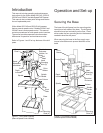
The drill press is shipped with the table and drill head
supported by wooden blocks near the bottom of the
column.
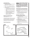
The head is raised to the operating position using a
strap and hoist, then secured to the column by
tighening the hex cap screw . The table is raised to
the desired position using the crank handle.
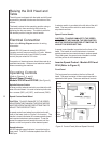
Electrical Connection
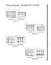
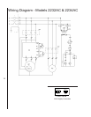
Refer to the Wiring Diagram section for wiring
information.
Models 2221VS (manual control) and 2232AC
(inverter control) are pre-wired for 115 volts. Models
2223VS (manual control) and 2234AC (inverter
control) are pre-wired for 220 volts.
Connection of electrical power should be made by a
qualified electrician. Observe local electrical codes
when connecting the machine.
Operating Controls
(Refer to Figures 3, 4, and 5)
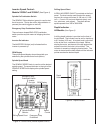
Manual Speed Control -
Models 2221VS and 2223VS (See Figure 3)
Spindle Selector Switch
A three-position selector switch is provided at the left
side of the drill head. It is used to select spindle rota-
tion: reverse (REV), off (OFF), and forward (FWD).
Speed Control Hand Wheel
CAUTION: TO AVOID DAMAGE TO THE SPEED
ADJUSTMENT MECHANISM, THE DRIVE MOTOR
MUST BE OPERATING BEFORE ATTEMPTING TO
ADJUST THE SPEED SETTING.
A speed control hand wheel is provided on the left
front of the head (refer to Figure 3 for location). The
handle is turned clockwise to increase spindle speed
and counterclockwise to educe speed. To set the
speed, the speed control handle is turned until the
pointer on the front panel is at the desired speed.
Speed Indicator
An LED spindle speed indicator is provided on the
front panel. The LED indicates speeds from 300 to
2000 rpm.
A selector switch is provided at the left side of the drill
head. The two-position switch is used to start and
stop the drive motor.
Speed Control Handle
CAUTION: TO AVOID DAMAGE TO THE SPEED
ADJUSTMENT MECHANISM, THE DRIVE MOTOR
MUST BE OPERATING BEFORE ATTEMPTING TO
ADJUST THE SPEED SETTING.
A speed control handle is provided on the front of the
head. The handle is turned clockwise to increase
spindle speed and counterclockwise to reduce speed.
To set the speed, the speed control handle is turned
until the pointer is at the desired speed.
Inverter Speed Control - Models 2232 and
2234 (Refer to Figure 2)
Front Panel
The front panel is mounted on the front of the drill
head. The panel contains all the controls required to
operate the drill press. There are additional controls
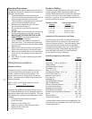
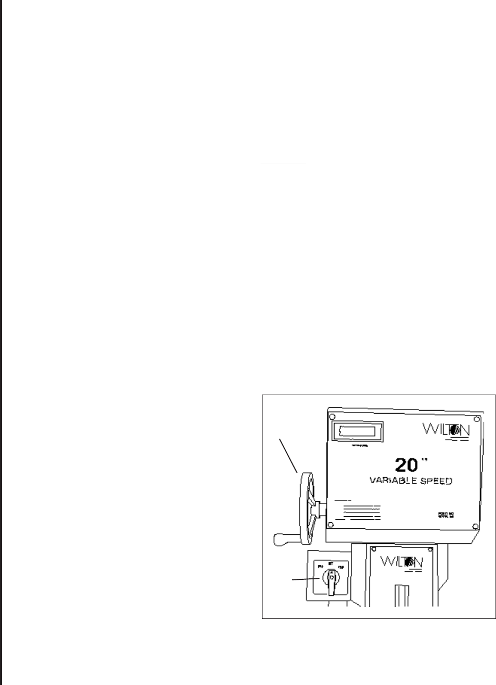
Figure 3: Control Panel (Manual Speed Control)
Speed
Control
Handwheel
Drive
Motor
Switch