


9
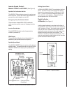
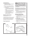
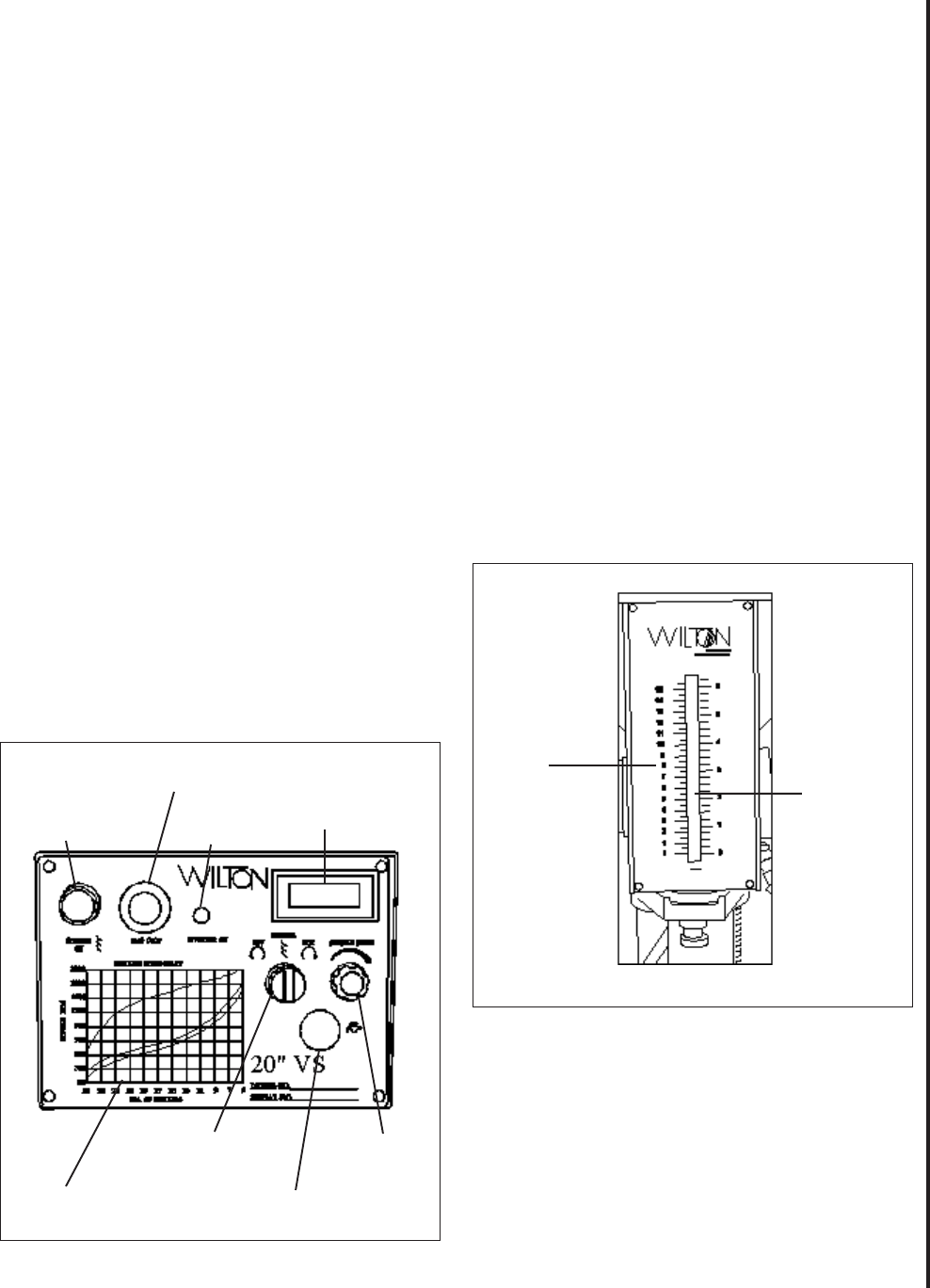
Figure 4: Control Panel (Inverter Speed Control)
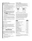
Drilling Speed Chart
A DRILLING SPEED CHART is provided on the front
panel. The chart can be used to select the speed
required for various drill sizes (0.196 inch to 1.000
inch — 5 mm to 25 mm) and materials (steel, cast
iron, aluminum, and copper). The chart defines
spindle speeds from 300 to 3000 RPM.
Depth Indicator —
All Models (See Figure 5)
A drilling depth indicator is provided on the front of
the drill head. The indicator can be set for depths up
to 6.5 inches (16.5 mm). A knurled knob is provided
at the at the front, underside of the head. Before
starting the motor, set the end of the drill against the
surface into which the hole is to be drilled. The
indicator is zeroed out using the knurled knob. The
motor is started and the hole drilled until the indicator
pointer reaches the desired depth.
Inverter Speed Control -
Models 2232AC and 2234AC
(See Figure 4)
Spindle On Pushbutton Switch
The SPINDLE ON pushbutton (green) is used to start
the drive motor. To stop the motor, the pushbutton is
pressed (the switch toggles on and off).
Emergency Stop Pushbutton Switch
The mushroom-shaped EMG. STOP pushbutton
switch provides a quick means of stopping the drive
motor.
Inverter On Indicator
The INVERTER ON light (red) indicates that the
inverter is powered up.
RPM Display
The spindle speed display shows the spindle rpm
selected by the spindle control knob (below).
Spindle Speed Knob
The SPINDLE SPEED knob is used to set the desired
spindle speed. The speed indicator to the right of the
SPINDLE SPEED knob displays the spindle speed
setting.
Figure 5: Depth Indicator
Depth
Scale
Indicator
Inverter
On Light
RPM Display
Emergency Stop
Pushbutton
Drilling Speed Chart
Spindle Direction
Selector
Emergency Stop
Pushbutton Switch
Speed
Control