


90-0115-00
10/97 Fltman.pm65
32
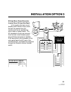
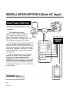
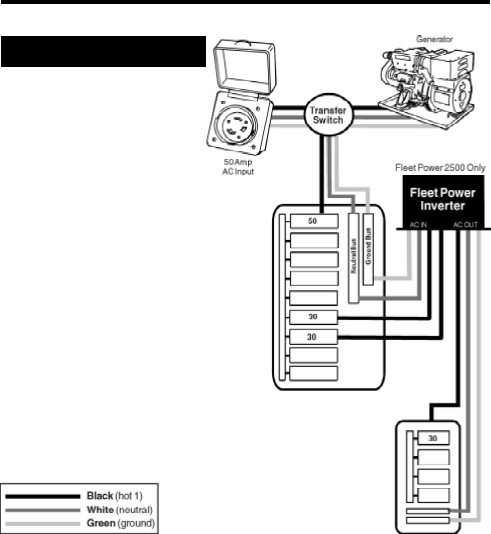
INSTALLATION OPTION 4 (Dual AC Input)
Fleet Power 2500 Only
• 50 Amp 120 Volt Shore Power Service
• Generator
The transfer switch shown,
switches, either manually or automati-
cally, between generator and shore
power. This switch is unrelated to the
transfer switch inside the Fleet Power 2500.
This AC panel has a single 120 volt leg.
The transfer AC input and the Charger AC
input are fed from separate 30 Amp circuit
breakers. Make sure the wiring between the AC
panel and the inverter will safely carry two 30
Amp circuits. Typically, a minimum of 10 AWG
wires would be used. 6 each (2 hot, 2 neutral
and 2 ground).
Please note that the inverter AC output
breakers are isolated from the main panel.
Keeping the inverter loads isolated is
important. Do not back feed the unit by supply-
ing AC from shore or generator to the inverter
AC output. Three inverter breakers are shown
in the particular diagram. You are not limited to
three breakers.