90-0115-00
10/97 Fltman.pm65
DC WIRING OPTIONS
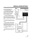
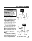
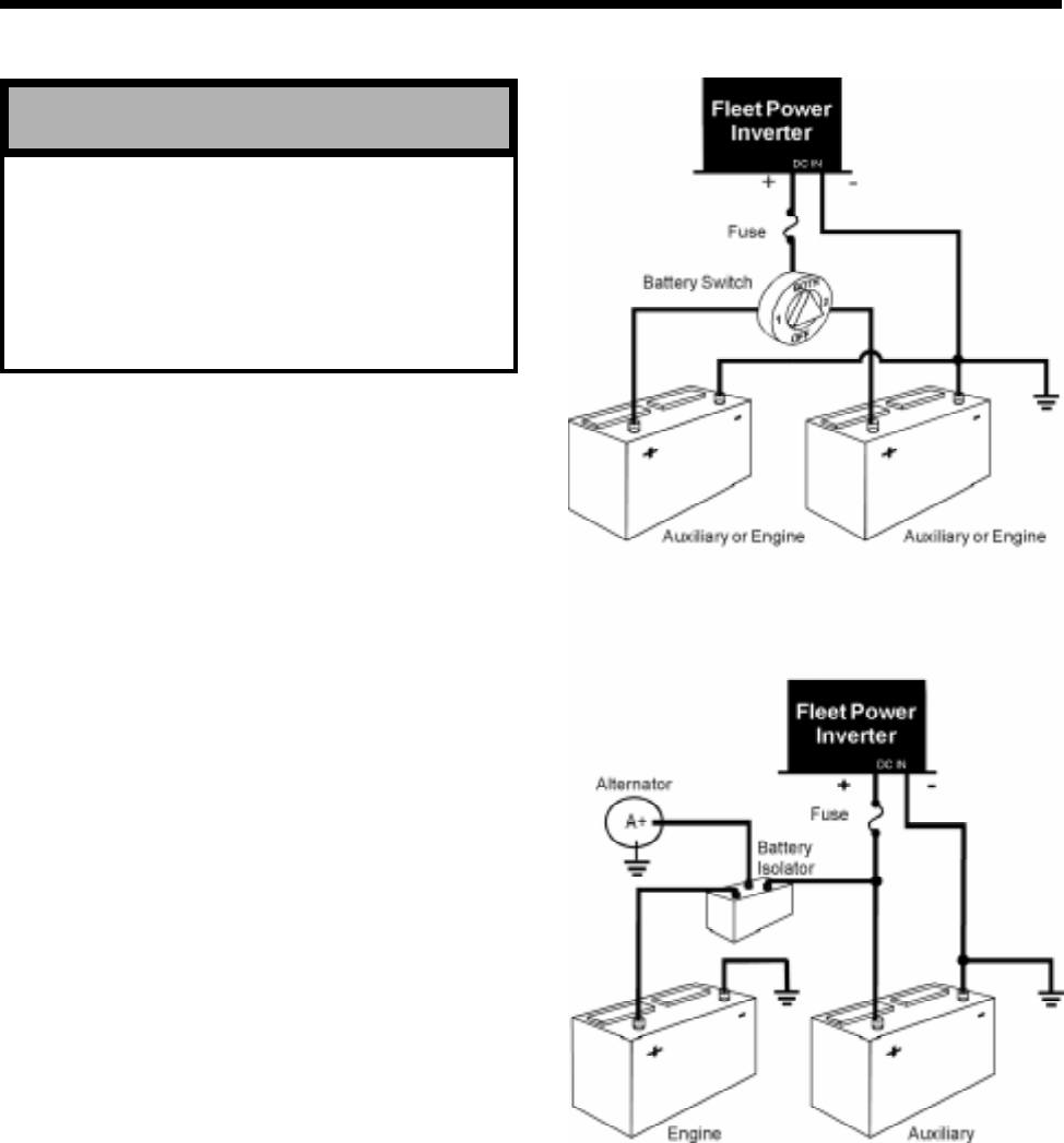
DC Wiring #1 - Two Battery* System
Using Manual Battery Switch
This system is simple and effective,
providing the user with the ability to choose
between either battery for inverter use or
charging.
When charging, the battery switch is
typically left in the "All" or "Both" position so
that both batteries are charged. When
using the inverter, the inverter battery
should be selected with the battery switch.
The inverter/charger's negative battery
cable should be connected directly to the
battery that will normally supply the inverter.
A fuse should be installed in the positive
cable within 18 inches of the battery. If the
cables to the switch exceed 18 inches, each
cable will require a fuse.
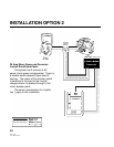
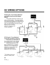
DC Wiring #2 - Two Battery* System
Using an Isolator for Charging both
Batteries
This allows charging of both batteries
from an alternator, but the inverter can only
draw power from the auxiliary battery. This
prevents accidental discharge of the engine
battery by the inverter. A paralleling sole-
noid can be used in place of the isolator.
33
* Each battery shown can represent
a battery bank.
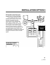
For Installations using Battery
Switches NOTE: No other DC loads
should be connected to the common on
the battery switch. This will prevent their
operation directly from charger power
when the battery switch is OFF.
WARNING


