


25
AC Wiring
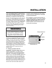
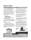
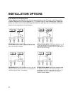
Determine which knockout(s) on the front
or side panels will be utilized and remove them
from the inverter. Note: Only remove the
knockout you will use to route the AC wires,
leaving the other knockout(s) intact. Install a
strain relief in knockout holes. Depending upon
which model you have, there can be one or
two AC inputs and one or two AC outputs
within the AC wiring compartment. The labeling
for the pigtails is on the front of the unit.
Conventional metal or plastic strain reliefs
may be used or 3/4 inch conduit fittings if the
wiring will be routed through a conduit.
Appropriate wire gauges must be used
throughout the installation. Refer to NEC
specifications.
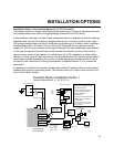
AC Input: All inputs from other AC
sources must be protected by branch circuit
rated breakers.
In the United States, no additional circuit
breakers are required between the inverter/
charger and the loads if the AC input service to
the inverter/charger is protected by a 15 or 20
ampere branch circuit rated breaker. This also
applies to Dual Input models (Freedom 25 and
30) where the inputs may be 15 or 20 amperes
each. In Canada, 15 ampere branch circuit(s)
maximum shall provide the service.
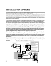
If a 30 ampere service supplies the
inverter/charger, additional 20 ampere (15
ampere in Canada) maximum branch circuit
INSTALLATION
rated breakers will be required between the
inverter/charger AC output and the loads.
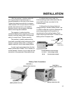
Feed the AC input wire(s) through the
knockout and into the AC wiring compartment.
Allow 6 inches of individual insulated black,
white and green wire to work with. Strip
approximately 1/2 inch of insulation off each
conductor and connect to the compression
terminal block: Black to Black, White to White,
and Green to Green.
You may choose to use butt splices (not
included) to make the wire connections.
AC Output: Feed AC output wire group(s)
through the knockout. Remember to allow 6
inches of individual insulated black, white and
green wire to work with. Strip 1/2 inch of
insulation off each conductor and connect to
the compression terminal block: Black to
Black, White to White, and Green to Green.
Tug firmly on each connection to make
sure they are secure. Later, if the unit is not
operating properly, check these connections
first. Carefully tuck the wires into the AC wiring
compartment. Secure the cover plate over the
electrical compartment. The cover plate is in
the accessory package.
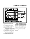
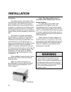
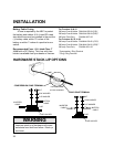
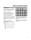
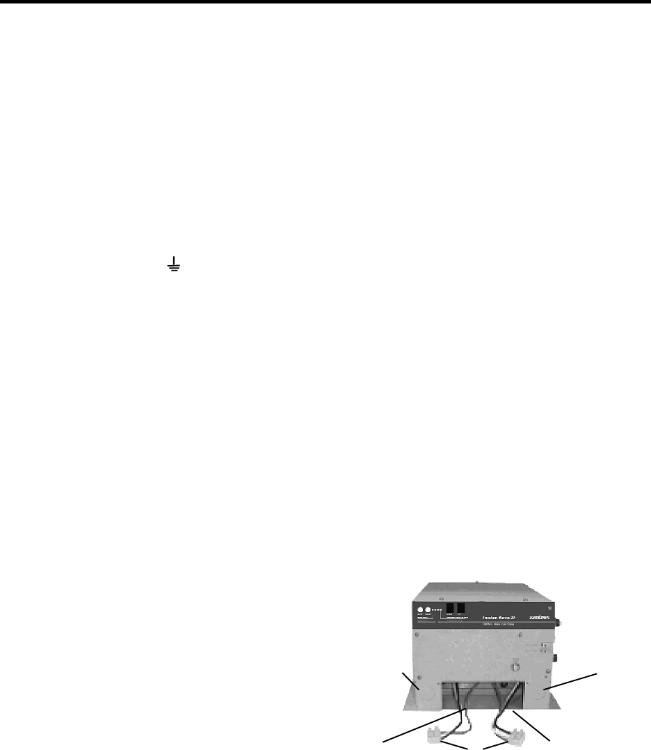
AC Electrical Wiring Compartment
Ground/green ......... Green to Green
Neutral/white ...........N White to White
Hot or Line/black .....L Black to Black
AC INPUT
COMPRESSION
TERMINAL
BLOCK
installed
KNOCKOUT
KNOCKOUT
AC OUTPUT