


29
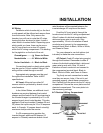
INSTALLATION OPTIONS
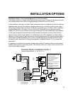
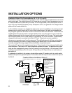
Installation Options
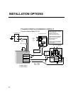
Installation options 1, 2, 3, and 4 are the most
commonly used applications involving specific
shorepower connections, generator power
options, and AC load configurations.
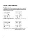
Shorepower configurations:
Systems with one 30 amp single phase
shorepower source with optional generator
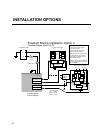
Systems with two 30 amp shorepower
sources with optional generator
Systems with a 50 amp 120 volt single phase
(3 wire) shorepower source with optional generator
Systems with a 50 amp 120/240 volt split
phase (4 wire) shorepower source with optional
generator
Inverter/charger configurations:
Single Input/Single Output Freedom Marine
Model 10, 15, 20
Dual Input/Dual Output Freedom Marine Model
25 and 30
• Can be connected with single in/single out
mode
• Can be connected with dual in/single out
mode
• Can be connected with dual in/dual out
mode
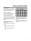
lanimoN
tnerruC
htgneLybGWAelbaC
)cirtem(
ledoMeziSesuFspmACD.tf3–1.tf6–3.tf01–6
01-FCDA002A001220/1
51-FCDA002A0510/10/10/2
02-FCDA003A0020/20/20/3
52-FCDA003A0520/20/30/3
03-FCDA053A0030/30/30/4
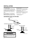
General Guide for Fuse Size and DC Cable Size*
*This guide is intended to provide general
recommendations for fuse and cable sizing.
Always consult Local and National Electrical
Codes for proper fuse and cable size prior to
installation.
Note: The chassis grounding wire must be no
smaller than 1 gauge under that of the positive
battery cable.