


8
Specifications
GC2020C Compressor/Limiter Owner’s Manual
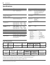
Specifications
Input Characteristics
Output Characteristics
In these specifications, when dB represents a specific voltage, 0 dB is referenced to 0.775 Vrms.
XLR type connectors and phone jacks (TRS) are balanced. (T=HOT, R=COLD, S=GND)
Sensitivity is the level required to produce an output of +4 dB (1.23 V).
Frequency Response 0
+1
dB 20 Hz— 20 kHz @+4 dB Link OFF/ON
Total Harmonic Distortion Less than 0.05% (THD + N)
20 Hz — 20 kHz @+4 dB
Controls
(per CH.)
Input Level, Output Level,
Exp. Gate (with ON/OFF switch),
Comp. Ratio, Threshold Level,
Attack Time, Release Time,
Comp switch
Hum & Noise (Average,
Rs=600
Ω
) (Measured with
BPF 20 Hz — 20 kHz)
–85 dB Power
Consumption
20W
Compression Ratio 1 : 1 —
∞
: 1
(Maximum limiting 32 dB)
Power
Requirement
USA and Canada
120 V 60 Hz
GENERAL
230 V 50 Hz
Compressor/Limiter
Threshold Level
+20 dB — –35 dB
(Input Control at 0 : +20 dB — +5 dB)
(Input Control at 5 : +20 dB — –20 dB)
(Input Control at 10 : +5 dB — –35 dB)
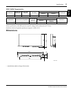
Dimensions
(W
×
H
×
D)
480
×
49.4
×
246mm
Expander Noise Gate
Threshold
+0 dB — –80 dB
(Input Control at 0 : 0 dB — –40 dB)
(Input Control at 5 : –25 dB — –65 dB)
(Input Control at 10 : –40 dB — –80 dB)
Weight 3.2kg
Attack Time 0.2 ms — 20 ms
* Measurement conditions
Link switch............................OFF
Input Level............................5 (center)
Output Level .........................5 (center)
Exp. Gate..............................switch OFF
Comp. Ratio..........................1 : 1 (minimum)
Threshold Level .....................0 (minimum)
Attack Time...........................0.2 ms (minimum)
Release Time.........................50 ms (minimum)
Key switch.............................INT
Release Time 50 ms — 2.0s
Gain Reduction 5 Segment LED Meter
Peak Indicators Red LED on each channel lights up when
the output signal is 3 dB below clipping.
Signal Indicators Green LED on each channel lights up
when the output signal is 17 dB below
the nominal level.
Connection
Actual Load
Impedance
For Use With Nominal Sensitivity
Input level
Connectors
Nominal
Maximum Before
Clipping
INPUT 15 kΩ 600 Ω Lines +4 dB (1.23 V) +4 dB (1.23 V) +20 dB (7.75 V)
XLR-3-31 Type
Phone Jack
Connection
Actual Source
Impedance
For Use With
Nominal
Output Level
Connectors
Nominal
Maximum Before
Clipping
OUTPUT 150 Ω 600 Ω Lines +4 dB (1.23 V) +20 dB (7.75 V)
XLR-3-32 Type
Phone Jack
–3