


6
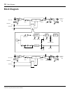
Controls & Connections
GC2020C Compressor/Limiter Owner’s Manual
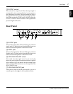
Controls & Connections
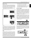
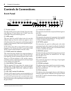
Front Panel
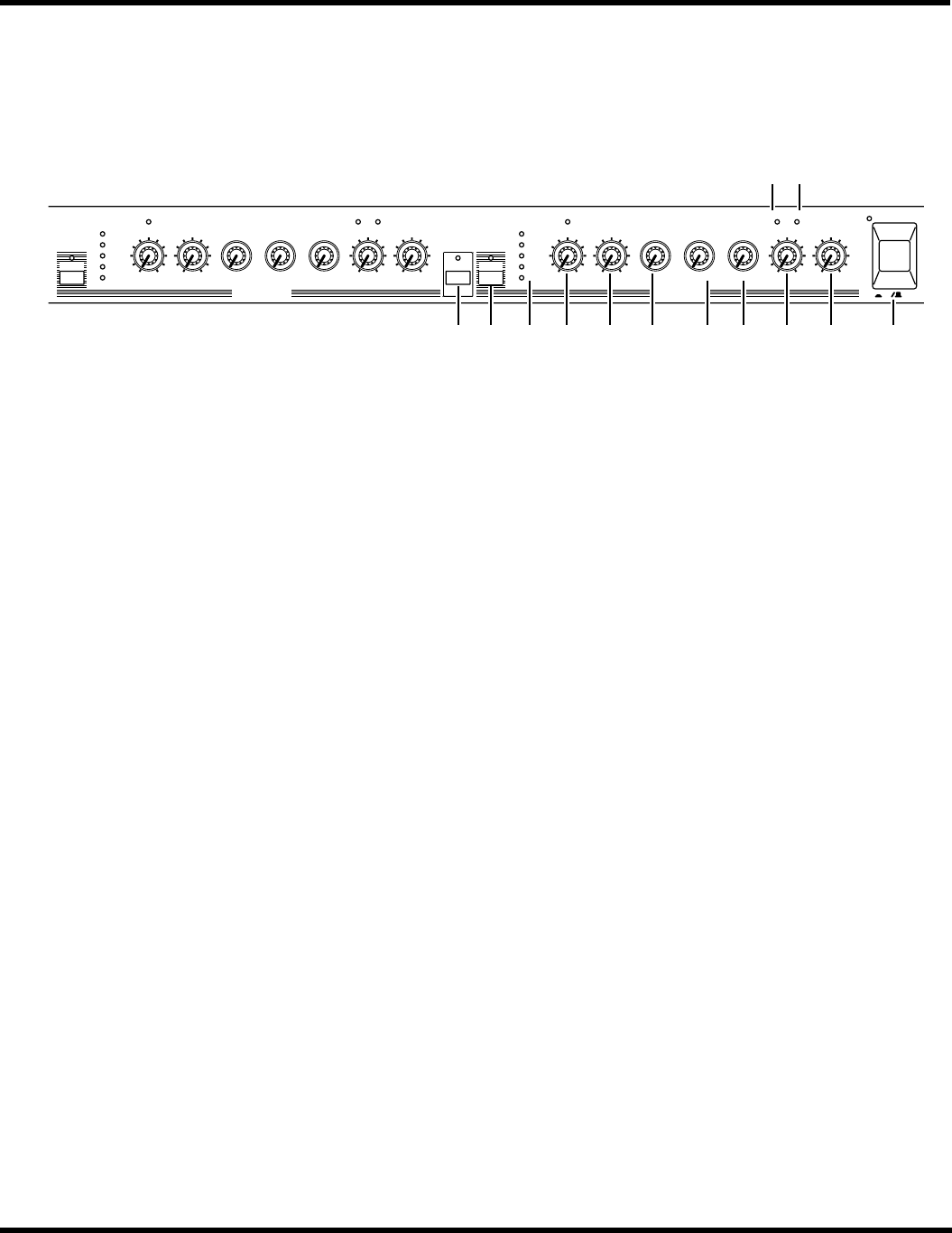
1
POWER Switch
Press this switch to power up the GC2020C. The power indi-
cator lights up. To power down the GC2020C, press this
switch again. The power indicator goes out.
2
LINK switch
This turns Link ON and OFF. When Link is ON, the LED
indicator lights up. Press the switch once again to turn it
OFF. When Link is ON, compression and limiting is applied
equally to both channels, so that a stereo signal can be pro-
cessed correctly.
NOTE: When using Link, set the COMP switch on both
channels to ON. And set the INPUT control and COMP
RATIO control on both channels to the same values.
3
COMP switch & indicator
This switch determines whether the compressor/limiter is
active, or bypassed. When this switch is ON, the LED indi-
cator lights up, and the compressor/limiter circuit is active.
When it is OFF, the indicator is OFF, and the compres-
sor/limiter circuit is completely bypassed, so the input signal
is sent straight to the output jack.
4
GAIN REDUCTION meter
This five-segment LED meter shows the amount of gain
reduction that is being applied by the compressor/limiter.
The LEDs indicate 0 dB, –4 dB, –8 dB, –16 dB, and –24 dB of
gain reduction.
5
EXP GATE control & indicator
The EXP GATE control is used to set the threshold level of
the expander gate. When this control is turned hard left, the
gate function is OFF. The LED above the EXP GATE control
shows the operation of the expander gate, and light up when
the gate is closed.
6
THRESHOLD control
This sets the level at which the compressor/limiter begins to
take effect.
7
RATIO control
This determines the amount of compression that is applied
to signals that exceed the threshold level. The range is from 1
(1:1 ratio) to infinity (infinity:1 ratio).
8
ATTACK control
This determines the speed (in milliseconds) with which
compression begins after a signal exceeding the threshold is
detected. The range is from 0.2 msec (very fast attack time)
to 20 msec (relatively slow attack).
9
RELEASE control
This determines the speed at which compression is removed
after the signal falls below the threshold level. The range
from 50 msec to 2 sec.
0
INPUT control
This controls the input level. A wide range of input signals
can be accommodated.
A
SIGNAL indicator
This indicator shows that a signal is present in the compres-
sor/limiter. It lights up when the output signal is 13 dB
below the nominal level.
B
PEAK indicator
This indicator shows that a signal is about to clip. It lights up
when the output signal is 3 dB below the clip point. Adjust
the OUTPUT control so that this indicator just lights up at
the loudest signals.
COMP
GAIN
REDUCTION
0
–4
–8
–16
–24
EXP GATE THRESHOLD RATIO ATTACK RELEASE INPUT OUTPUT
CHANNEL A CHANNEL B
SIGNAL PEAK
GAIN
REDUCTION
0
–4
–8
–16
–24
EXP GATE THRESHOLD RATIO ATTACK RELEASE INPUT OUTPUT
SIGNAL PEAK
LINK COMP
ON OFF
POWER
0 10 0 10 0 10 0 10
1
2
48
20
00
0.2
1
35
10
20
0.05
0.1
0.3 0.5
1
2
0 10 0 10 0 10 0 10
1
2
48
20
00
0.2
1
35
10
20
0.05
0.1
0.3 0.5
1
2
secms
secms
10C98765432
BA