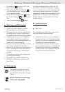
Preparing for use / Operation
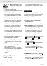
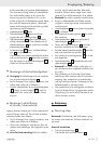
j Insert the disc cover guide
7
with the coded
projection
9
in the coded groove
16
.
j Turn the disc guard cover
7
into the desired
position (working position). The closed side of
the disc guard cover
7
must always be facing
the operator.
j Close the clamping lever
8
to firmly clamp
the disc guard cover
7
in place.
If necessary the clamping force of the connection
can be adjusted by tightening or loosening the
adjuster screw
10
.
Ensure that the disc guard cover
7
sits firmly
on the spindle collar.
Q
Attaching the auxiliary handle
m Caution! For safety reasons this device must
always be used with the auxiliary handle
6
in
place.
J Pull the mains plug out of the mains socket be-
fore you carry out any task on the device.
j Screw the auxiliary handle
6
on the left, right
or on the top of the head of the device.
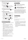
Q
Attaching and replacing
roughing / grinding / cutting discs
Take note of the dimensions of the roughing / grind-
ing or cutting discs. The circular hole must fit on to
the mounting flange without play. Do not use a re-
ducer piece or adapter.
J Pull the mains plug out of the mains socket be-
fore you carry out any task on the device.
J Check the condition of the roughing / grinding
or cutting discs. They must be free of damage,
moisture or cracks.
m Danger of burns! Always wear protective
gloves when changing a roughing / grinding or
cutting disc. Roughing / grinding and cutting
discs become hot during use. Do not touch
them until after they have cooled down.
j Note: Always ensure the discs are free of dirt
before use.
j Use only abrasive consumables or tools with
an allowable speed at least as high as the no-
load speed of the device.
j Press the spindle lock button
11
only after the
mounting spindle
14
has reached a standstill.
j Press the spindle lock button
11
to block the
drive.
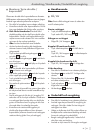
j Release the clamping nut
13
using the spanner
17
, Fig. C.
j Place the roughing / grinding or cutting disc on
to the mounting flange
15
with its labelled side
facing towards the device.
j Then replace the clamping nut
13
, with its
raised side facing upwards, on to the mounting
spindle
14
.
j Press the spindle lock button
11
to block the
drive.
j Tighten the clamping nut
13
again with the
spanner
17
.
j Note: Replace a new disc immediately if it
runs unevenly or vibrates after being exchanged.
j After replacing a disc let the device run under
no-load conditions for 30 seconds as a safety
check. Look out for unusual noises or generation
of sparks. Check that all the fastened-on parts
are correctly attached.
j Pay attention to see that the arrow showing the
direction of rotation on the roughing / grinding
or cutting discs (including diamond cutting discs)
corresponds with the direction of rotation of the
device (see arrow on the head of the device).
Q
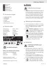
Operation
Q
Switching on and off
Note: Always switch on the angle grinder before
bringing it into contact with the workpiece material.
Switching on the device
j Press the safety lock-out
3
.
Then press the ON / OFF switch
2
Switching off the device
j Release the ON / OFF switch
2
.