


A
OPTIONAL CABLE SPECIFICATIONS
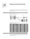
The tables in this appendix describe the pinouts for the cables that you can use
with Router 3000 series routers. P
ins that are not described in the following tables
are not connected.
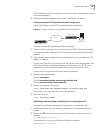
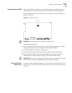
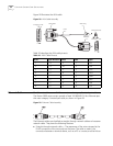
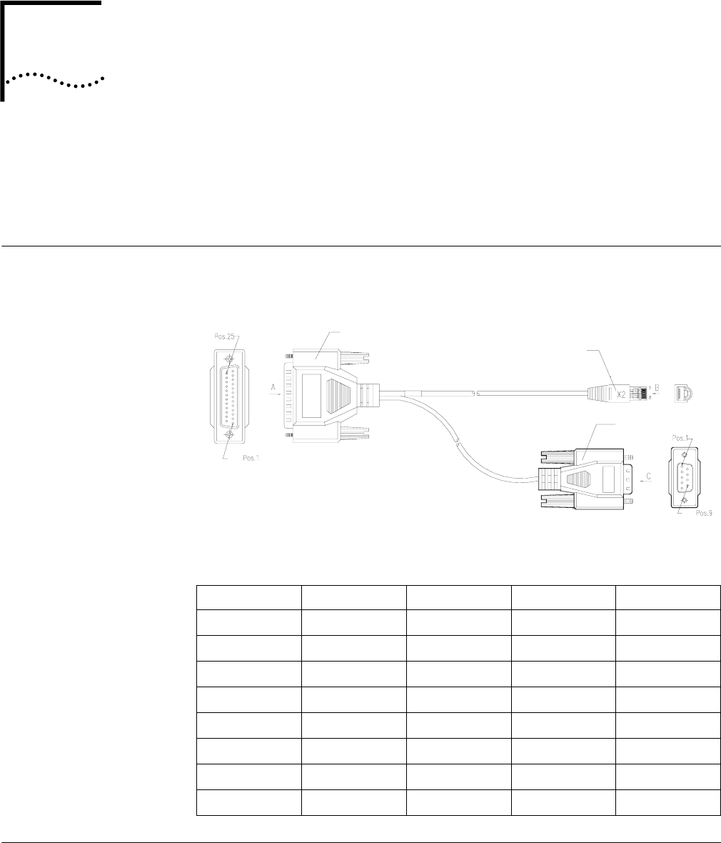
Console Cable Figure 27 illustrates the console cable.
Figure 27 Console Cable Assembly
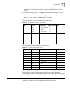
Table 25 describes the console cable pinouts.
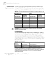
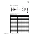
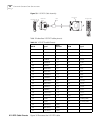
AUX Cable The AUX cable is an 8-core shielded cable. One end of the cable has an RJ-45
connector and connects to the AUX port of the router. The other end has both a
DB-25 (male) adapter and a DB-9 (male) adapter. Use the appropriate connector
for the port on the modem.
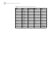
Table 25 Console Cable Pinouts
RJ-45 Signal Direction DB-25 DB-9 Signal
1 —> 5 8 CTS
2 —> 6 6 DSR
3 —> 3 2 RXD
4 <— 8 1 DCD
5 - 7 5 GND
6 <— 2 3 TXD
7 <— 20 4 DTR
8 <— 4 7 RTS
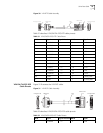
Enlarged A side
DB25 Female
8P8C Plug
Enlarged B side
DB9 Female
Enlarged C side