


Serial Port Cable 59
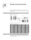
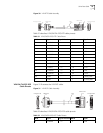
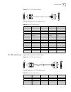
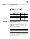
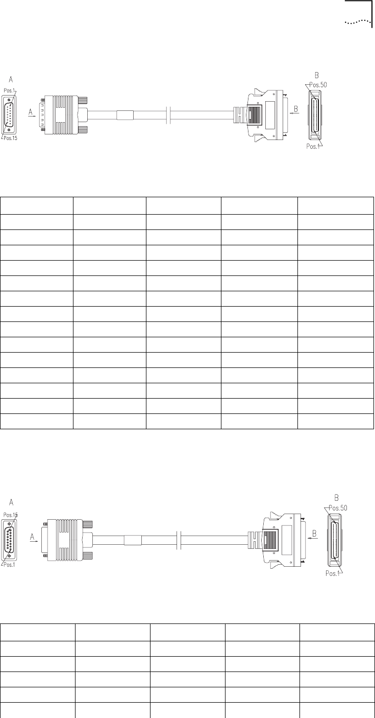
Figure 34 X.21 DTE Cable Assembly
Table 35 describes X.21 DTE cable pinouts.
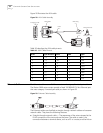
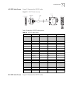
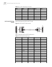
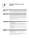
X.21 DCE Cable Pinouts Figure 35 illustrates the X.21 DCE cable.
Figure 35 X.21 DCE Cable Assembly
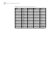
Table 36 describes X.21 DCE cable pinouts.
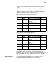
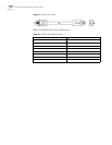
Table 35 X.21 DTE Cable Pinouts
DB50 Signal Signal Direction Signal DB15
7 GND <--> Circuit GND 8
23 DTE/DCE - Circuit GND 8
50 GND <--> Shield GND 1
10 RTS/CTS+ -> Control+ 3
34 RTS/CTS- -> Control- 10
38 CTS/RTS+ <- Indication+ 5
14 CTS/RTS- <- Indication- 12
20 RXD/TXD+ <- Receiver+ 4
44 RXD/TXD- <- Receiver- 11
15 TXD/RXD+ -> Transmit+ 2
39 TXD/RXD- -> Transmit- 9
19 RXC/TXCE+ <- Timing+ 6
43 RXC/TXCE- <- Timing- 13
- Shielding sheath <--> Shielding sheath -
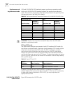
Table 36 X.21 DCE Cable Pinouts
DB50 Signal Signal Direction Signal DB15
7 GND <--> Circuit GND 8
50 GND <--> Shield GND 1
10 RTS/CTS+ -> Indication+ 5
34 RTS/CTS- -> Indication- 12
38 CTS/RTS+ <- Control+ 3