30 CHAPTER 2: INSTALLING THE SWITCH
The -48V DC power will take priority over the AC mains and will power
the Switch if it is connected.
Connecting the
Earthing Cable
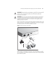
Use the earthing cable that accompanies your Switch if the length is
suitable. Alternatively use the earthing cable specification as defined in
Appendix B on page 91.
The earthing cable is only required if the Switch is powered by the RPS
only.
The recommended cable length should not exceed 3 metres (9.84 feet).
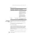
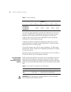
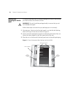
RPS LED The RPS status LED on the front of the Switch 4500 PWR indicates the
status of the RPS and AC supplies as shown in
Table 9.
Table 9 RPS LED Colors
Using Power over
Ethernet
The Switch 4500 Power over Ethernet (PoE) units can supply power to
any IEEE 802.3af compliant device through any of its 10/100 ports over a
Category 5 or Category 5e Ethernet cable. The same cable connects the
device to the network.
Power over Ethernet is a self-configuring protocol. When you plug a PoE
compliant device into one of the ports on the Switch, the Switch will
supply the power required to the device, providing that the total power
budget for the Switch would not be exceeded by doing so.
A PoE Switch combines the functionality of a standard Ethernet Switch
with a single power supply that can power multiple devices. Using a PoE
Switch has the following advantages over an unpowered network:
■ Reduced Cabling — a PoE (802.3af) compliant device which has its
power supplied over its ethernet cable does not require a separate
power supply. If, for example, the Switch is used to connect a 3Com
11 Mbps Wireless LAN Access Point 8500 to the network, then only a
Color State
Green AC and RPS supply connected.
Yellow AC failed or not connected. RPS supply is ok.
Off There is no RPS supply connected.


