7 8
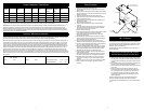
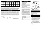
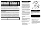
ProductConguration/Specications
Model
Number
Speed RPM Collet Size in.
(mm)
Neck Type Net Wt. kg
(lb.)
Length mm
(in.)
*Noise Level
dBA Pressure
(Power)
**Vibration
Level m/s ²
(ft/s ²)
**Uncertainty K
m/s ²
28627 18,000 ¼(6.35) Short 522(1.15) 184(7.25) 86.1(97.7) 2.91(9.56) 0.15
28628 18,000 ¼(6.35) Extended 690(1.52) 266(10.5) 77.9(89.5) 1.41(4.62) 0.04
28629 25,000 ¼(6.35) Short 405(0.89) 152(6.0) 80.2(91.8) 1.98(6.56) 0.14
28630 25,000 ¼(6.35) Extended 639(1.40) 247(9.75) 79.4(91.0) 4.51(14.8) 0.12
*Declarednoiselevels;measurementscarriedoutinaccordancewithstandardENISO15744.
**DeclaredvibrationlevelsinaccordancewithEN12096;measurementscarriedoutinaccordancewithstandardENISO8662-13.
IMPORTANTNOTE:Thenoiseandvibrationvaluesstatedinthetablearefromlaboratorytestinginconformitywithstatedcodesandstandardsandarenot
sufcientriskevaluationforallexposurescenarios.Theactualexposurevaluesandamountofriskorharmexperiencedtoanindividualisuniquetoeach
situationanddependsuponthesurroundingenvironment,thewayinwhichtheindividualworks,theparticularmaterialbeingworked,workstationdesign,as
wellasupontheexposuretimeandthephysicalconditionoftheuser.3Mcannotbeheldresponsiblefortheconsequencesofusingdeclaredvaluesinsteadof
actualexposurevaluesforanyindividualriskassessment.
Operating/MaintenanceInstructions
PRIORTOTHEOPERATION
Thetoolisintendedtobeoperatedasahandheldtool.Itisalwaysrecommendedthatwhileusingthetool,operatorsstandonasolidoor,inasecureposition
witharmgripandfooting.Beawarethatthesandercandevelopatorquereaction.SeethesectioninSAFETYPRECAUTIONSin.
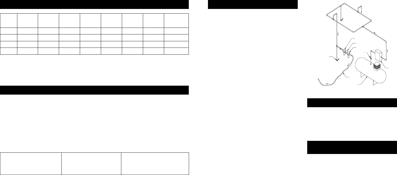
Useacleanlubricatedairsupplythatwillgiveameasuredairpressureatthetoolof6.2bar(90psig)whenthetoolisrunningwiththeleverfullydepressed.Itis
recommendedtouseanapproved10mm(3/8in)x8m(25ft)maximumlengthairline.ConnectthetooltotheairsupplyasshowninFigure1.Donotconnect
thetooltotheairlinesystemwithoutaneasilyaccessibleairshutoffvalve.Itisstronglyrecommendedthatanairlter,regulatorandlubricator(FRL)beused
asshowninFigure1asthiswillsupplyclean,lubricatedairatthecorrectpressuretothetool.Inanycaseappropriateairpressureregulatorsshallbeusedat
alltimeswhileoperatingthistoolwherethesupplypressureexceedsthemarkedmaximumofthetool.Detailsofsuchequipmentcanbeobtainedforyourtool
distributor.Ifsuchequipmentisnotused,thetoolshouldbemanuallylubricated.Tomanuallylubricatethetool,disconnecttheairlineandput2to3dropsof
suitablepneumaticmotorlubricatingoilsuchas3M™AirToolLubricantPN20451,FujiKosanFK-20orMobilALMO525intothehoseend(inlet)ofthetool.
Reconnecttooltotheairsupplyandruntoolslowlyforafewsecondstoallowairtocirculatetheoil.Ifthetoolisusedfrequently,lubricateitonadailybasisor
lubricateitifthetoolstartstosloworlosepower.Itisrecommendedthattheairpressureatthetoolbe6.2bar(90psig)whilethetoolisrunningsothemaximum
RPMisnotexceeded.Thetoolcanberunatlowerpressuresbutshouldneverberunhigherthan6.2bar(90psig).Ifrunatlowerpressuretheperformanceofthe
toolisreduced.
RecommendedAirline
Size-Minimum
RecommendedMaximumHoseLength AirPressure
10mm 3/8in 8meters 25feet MaximumWorkingPressure
RecommendedMinimum
6.2bar
N/A
90psig
N/A
SafetyPrecautions
1. Readallinstructionsbeforeusingthistool.Alloperatorsmustbefully
trainedinitsuseandawareofthesesafetyrules.
2. ThetoolRPMshouldbecheckedonaregularbasistoensureproper
operatingspeed.
3. Makesurethetoolisdisconnectedfromtheairsupply.Selectasuitable
abrasiveandsecureittothediscpadorspindle.Becarefultocenterthe
abrasiveonthediscpad.
4. Alwayswearrequiredsafetyequipmentwhenusingthistool.
5. Alwaysremovetheairsupplytothesanderbeforetting,adjustingor
removingtheabrasiveordiscpad.
6. Alwaysadoptarmfootingandgripandbeawareoftorquereaction
developedbythesander.
7. Useonly3Mapprovedspareparts.
8. Alwaysensurethematerialbeingworkedisrmlyxedtoavoid
movement.
9. Checkhoseandttingsregularlyforwear.Donotcarrythetoolbyits
hose;alwaysbecarefultopreventthetoolfrombeingstartedwhen
carryingthetoolwiththeairsupplyconnected.
10.Dustcanbehighlycombustible.
11.IftoolisservicedorrebuiltchecktoensurethatthemaximumtoolRPM
isnotexceededandthatthereisnoexcessivetoolvibration.
12.Donotexceedmaximumrecommendedairpressure.Usesafety
equipmentasrecommended.
13.Priortoinstallinganyshaftmountedabrasiveorsandingorgrinding
accessory,alwayscheckthatitsmarkedmaximumoperatingspeedis
equalorhigherthantheratedspeedofthistool.
14.Thetoolisnotelectricallyinsulated.Donotusewherethereisa
possibilityofcontactwithliveelectricity,gaspipes,and/orwaterpipes.
15.Thistoolisnotprotectedagainsthazardsinherentincuttingoperations,
andnosuchcuttingproductsshouldeverbeattached.
16.Takecaretoavoidentanglementwiththemovingpartsofthetoolwith
clothing,ties,hair,cleaningragsorloosehangingobjects.Ifentangled,
stopairsupplyimmediatelytoavoidcontactwithmovingtoolparts.
17.Keephandsclearofthespinningpadorspindleduringuse.
18.Ifthetoolappearstomalfunction,removefromuseimmediatelyand
arrangeforserviceandrepair.
19.Donotallowthetooltofreespinwithouttakingprecautionstoprotect
anypersonsorobjectsfromthelossoftheabrasiveorpadruptures.
20.Immediatelyreleasethestarthandleintheeventofanydisruption
ofpressure;donotattempttore-startuntilthedisruptionhasbeen
corrected.
21.Whentoolisnotinuse,storeinaclean,dryenvironmentfreeofdebris.
22.RecycleordisposeoftoolaccordingtoLocal,State,andFederal
regulations.
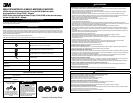
Figure1
Closed Loop Pipe System
Sloped in the direction of air flow
Drain Leg
Ball Valve
To Tool Station
Filter
Drain Valve
Regulator
Lubricator
Ball
Valve
Ball Valve
Air Flow
Air Dryer
Air Compressor
and Tank
Air Hose
To Coupler
at or near Tool
3M
™
DieGrinder
3M™DieGrinderaccessoriesaredesignedforuseon3MDieGrinders.
Constructedfrompremium,industrial-qualitymaterials,theirdurabilityand
preciseconstructionaretheidealcomplementtotheperformanceofthe3M
DieGrinder.SeeProductConguration/Specicationstableforthecorrect
replacementpadforaparticularmodel.
See3MASDAccessorycatalog61-5002-8098-9and61-5002-8097-1for
additionalAccessories.
Removingandremountingshanksandshaft
mountedabrasiveproductsintocolletchuck
1. Disconnectairlinefromtool.
2. Removecurrentlymountedshaftaccessory,shankorabrasiveproduct
fromcolletchuck*byusingthetwowrenchessuppliedwiththetool.Use
thewrenchtosecurethecolletbodywhileturningthecolletnutcounter
clockwise.
3. Aftertheexistingproducthasbeenremovedfromthecollet,inspectthe
colletinserttoensurethatisfreeofdebrisandundamaged.
4. Fullyinsertthenewshaftmountedaccessory,shankorabrasiveproduct
intothecollet.
5. Securethecolletbodywiththewrenchandtightenthecolletnut
securely.Alwaysusethecorrectsizedcolletwiththematchingshank
(use1/4incolletinsertwith1/4inshaftsor6mmcolletinsertwith
6mmshafts).Aninadequatelyinsertedshankcouldbendorbreak
causingdamagetothetoolandworkpieceandpossibleinjurytothe
operatororbystanders.
Note:Duringtheabovesteps,ensurethatallhardwareandabrasive
productsaremountedconcentricallyonthesupportingaccessory.
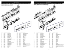
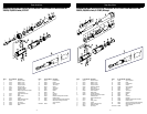
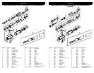
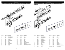
*InthedrawingsonthePartsPages,Figures1,2and3comprisetheCollet
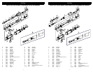
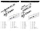
Chuck.


