Command Summary
109
C
Command Summary
Introduction
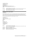
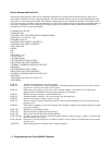
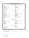
For convenience, a “quick reference” listing tabulating general command headers, and calibration command headers is
shown at the beginning of Table C-1 (page 110). (Note that calibration commands are described in detail in Appendix A.)
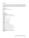
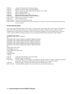
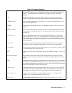
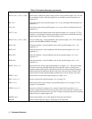
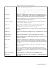
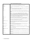
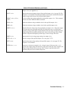
Table C-2 (pages 111-115) provides an alphabetical listing and a brief description of each command that may be sent to the
power supplies. Chapter 5 gives a complete description (including syntax) of most of the commands listed.
All of the commands can be executed remotely over the GP-IB. Many of the commands may also be executed locally from
the supply's front panel (marked by single asterisks in Table C-1).
Several commands will generate a response which will be indicated on the front panel of the supply. These commands are
indicated by double asterisks in Table C-1.
Command headers are accepted in upper or lower case letters although only upper case letters are used in this summary.
The brackets < > indicate a number to be sent.
Note that <ch> must specify an output channel number from 1 through 4 as applicable. Commas or spaces are required
between numbers. Spaces are optional between the command header and the first number. Use semicolons between
multiple commands sent in one statement.


