General Information
19
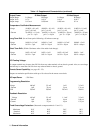
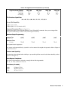
Table 1-3. Supplemental Characteristics (continued)
High Line Inrush Current: 100 V Opt 120 V Opt 220 V Opt 240 V Opt
Peak Value 85 A 85 A 50 A 50 A
rms Value 6.3A 5.7 A 3.0 A 3.0 A
Fuse Rating 8 A 8 A 4 A 4 A
GP-IB Interface Capabilities:
SH1. AH1, T6, L4, SR1, RL1, PP1, DC1, DT0, C0, E1
Current Sink Capability:
25 Watt output: 0.50 A
50 Watt output: 1.0 A (2.0 A below 16 V)
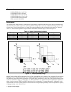
Command Processing Time: (see Figure 1-3)
7 milliseconds typical (with front panel disabled). Using STD and RCL commands allows you to change all the
voltage and current settings in about 10 mS (with front panel disabled).
Maximum Output Programming:
Response Time 6 mS 6 mS 6 mS 6 mS
Settling Band 50 mV 50 mV 50 mV 50 mV
Maximum Time
Constant
750
µ
S 750
µ
S 750
µ
S 750
µ
S
Series and Parallel operation:
Two outputs can be operated directly in parallel or can be connected for straight series operation. Refer to Chapter 4
for more information.
Reactive Load Capability:
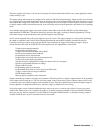
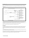
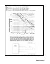
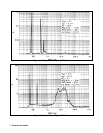
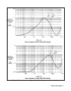
All outputs have been designed with the ability to operate with significant reactive loads without instability (refer to
Figures 1-4 through 1-6)
Safety Agency Compliance:
This series of power supplies is designed to comply with the following standards:
IEC 348, UL 1244, and CSA 22.2 No. 231.
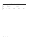
Dimensions (all models):
Height 132.6mm (5.22 in)
Width 425.5mm (16.75 in.)
Depth 497.8mm (19.6 in.)


