General Information
18
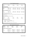
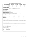
Table 1-3. Supplemental Characteristics (continued)
Output Power 25 Watt Output 50 Watt Output
Output Range Lo Range Hi Range Lo Range Hi Range
Output Volts 0-7 V 0-50 V 0-16 V 0-50 V
Output Amps 0-15 mA 0-500 mA 0-200 mA 0-2 A
Temperature Coefficient-Measurement:
Voltage (0.002% + 0.1 mV)
per° C +0.5 mV
(0.002% + 0.1 mV)
per° C +4 mV
(0.002% + 0.1 mV)
per° C +1 mV
(0.002% + 0.1 mV)
per° C +4 mV
±
Current (0.0025% + 1.5
µ
A)
per° C + 1
µ
A
(0.0025% + 10
µ
A)
per° C + 40
µ
A
(0.0025% + 20
µ
A)
per° C + 15
µ
A
(0.0025% + 50
µ
A)
per° C + 150
µ
A
Long Term Drift: (In an 8 hour period following a 30 minute warm up)
Voltage 0.006% + 0.5 mV 0.006% + 2 mV 0.006% + 0.5 mV 0.006% + 2 mV
+ Current
0.01% + 5
µ
A 0.01% + 20
µ
A 0.01% + 40
µ
A 0.01% + 60
µ
A
Short Term Drift: (Within 30 minutes after a line and/or load change):
Voltage 0.002 + 0.5 mV 0.002 + 1 mV 0.002 + 0.5 mV 0.002 + 1 mV
+ Current
0.01% + 2
µ
A 0.01% + 20
µ
A 0.01% + 25
µ
A 0.01% + 60
µ
A
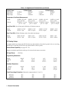
DC Floating Voltage:
No output terminal may be more that 240 Vdc from any other terminal or from chassis ground. Also, no overvoltage
terminal may be more than 240 Vdc from any other terminal or chassis ground.
Remote Sense Capability: (see pages 50 - 52):
Outputs can maintain specifications with up to 10 volt total in the remote sense leads.
AC Input Power
: 550 Watts
Programming Resolution:
Voltage
460
µ
V
3.2 mV 1 mV 3.2 mV
+ Current
1
µ
A 33
µ
A 13
µ
A 131
µ
A
OVP 230 mV 230 mV 230 mV 230 mV
Readback Resolution:
Voltage
483
µ
V
3.3 mV 1.1 mV 3.3 mV
+ Current
1 µA 48 µA 14 µA 160 µA
- Current
1 µA 37 µA 14 µA 151 µA
Fixed Overvoltage Protection: (Measured at output terminals +V and -V)
Minimum 56 V 56 V 56 V 56 V
Nominal 60 V 60 V 60 V 60 V
Maximum 64 V 64 V 64 V 64 V


