


85036B/E A-5
Standard Definitions
Nominal Standard Definitions
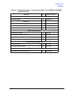
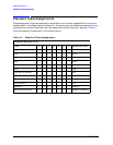
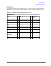
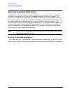
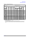
Table A-3 Standard Definitions
System Z
0
a
= 75 Ω
Calibration Kit Label: N 75 Ω
Standard
b
C0 ×10
−
15
F
C1 ×10
−
27
F/Hz
C2 ×10
−
36
F/Hz
2
C3 ×10
−
45
F/Hz
3
Fixed or Sliding
c
Offset Freq
(GHz)
Coax or Waveguide
Standard Label
d
Number
Type
Delay (ps)
Z
0
Ω
Loss (Ω/s)
Min
Max
1
Short
0751.1
3G
0999
Coax
Short (m)
d
2
Open
63.5 84 56 0 0 75 1.1
3G
0999
Coax
Open (m)
d
3
Load Fixed
0751.1
3G
0999
Coax Broad-
band
4
Delay/
Thru
0751.1
3G
0999
Coax Thru
5
6
7
Short
17.544 75 1.1
3G
0999
Coax
Short (f)
d
8
Open
41
e
40 5 0 17.544 75 1.1
3G
0999
Coax
Open (f)
d
a. Ensure system impedance (Z
0
) of network analyzer is set to this value.
b. Open, short, load, delay/thru, or arbitrary impedance.
c. Load or arbitrary impedance only.
d. Standard labels that specify sex, (m) or (f), refer to the sex of the analyzer’s test port connector.
e. If your instrument is an Agilent 8752B or 8711 Option 1EC, and you are calibrating at the test port, this number is 33. For all
other instruments and applications, including calibrating at a point other than the test port (such as the end of a cable), 41 is
the correct number. This is because the 8752B and 8711 Option 1EC have special female test ports with longer, more rugged
fingers.