


AT-FS238a/x and AT-FS238b/x Series Installation Guide
3
The back panel of the AT-FS238a/x and AT-FS238b/x Series Bridging
Converters features a receptacle power connector and DIP switches for
manually configuring the ports.
Note
The AT-FS238a/x and AT-FS238b/x Bridging Converters are designed
with 2 different receptacle connectors: 12VDC only or 12-50VDC version
models.
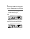
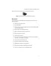
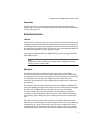
Figure 3 illustrates the back panel of the AT-FS238a/x or the AT-FS238b/x
Series Bridging Converters with 3-prong receptacle connector for the
12VDC version model.
Figure 3 Back Panel of the AT-FS238a/x and AT-FS238b/x Series Bridging Converters
(12VDC Receptacle Connector)
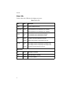
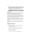
Figure 4 illustrates the back panel of the AT-FS238a/x and the AT-FS238b/x
Series Bridging Converters with the 3-prong receptacle connector for the
12-50VDC version model.
Figure 4 Back Panel of the AT-FS238a/x and AT-FS238b/x Series Bridging Converters
(12-50VDC 3-Prong Receptacle Connector)
DIP Switches
12VDC Receptacle Connector
DC Polarity Symbols
DIP Switches
12-50VDC 3-Prong Receptacle Connector
DC Polarity Symbols