


Installing the Bridging Converter
22
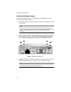
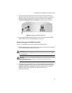
9. Connect the other end of the wires to the terminal block on the AT-
PWR237 power adapter.
Note
The terminal block on the AT-PWR237 does not have a connection for
the ground feed wire.
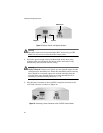
War ning
"Safety Hazard"- Check to see if there are any exposed copper strands
coming from the installed wires. When this installation is done correctly
there should be no exposed copper wire strands extending from the
terminal block. Any exposed wiring can conduct harmful levels of
electricity to persons touching the wires. 19
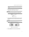
10. With the wires securely connected to both the input power connector in
the rear of the unit and the terminal block on the power source, plug the
other end of the power source to the power outlet. (Refer to “Technical
Specifications” on page 27 for power requirements.)
11. Power ON the end-nodes.
12. Verify that the LNK LEDs for both the fiber optic port and the twisted
pair port are green. If either LED is OFF, refer to “Troubleshooting” on
page 25 for instructions.
The bridging converter runs a series of self-diagnostic tests. Once the self
tests are complete, the converter is ready for normal network operations.