


Technical Specifications
30
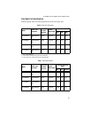
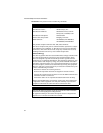
Table 8 Fiber Optic Datalink
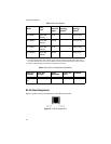
Table 9 Fiber Optic Loss Specification (Benchmark)
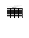
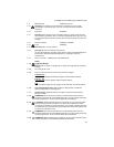
RJ-45 Pinout Assignments
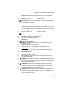
Figure 13 shows the pin assignments of the RJ-45 connector.
Figure 13 RJ-45 Pin Assignments
Model
Fiber
Type
1
1. SMF = Single-Mode Fiber
Minimum
Power/Link
Budget
Minimum
Operating
Distance
2
2. The recommended minimum range is stated in all cases where the maximum transmitter output power exceeds
the receivers saturation level. This is to prevent blinding or burning out of the optical receiver on the far-end node.
Maximum
Operating
Distance
3
3. Distance is calculated based on ideal situations without any other loss factor.
AT-FS238a/1 9/125 SMF
Simplex
6.0 dB 0 15 km (9.4 mi)
AT-FS238a/2 9/125 SMF
Simplex
16.0 dB 0 40 km (25 mi)
AT-FS238b/1 9/125 SMF
Simplex
6.0 dB 0 15 km (9.4 mi)
AT-FS238b/2 9/125 SMF
Simplex
16.0 dB 0 40 km (25 mi)
Fiber Type
1
-
Connector
1. SMF = Single-Mode Fiber
Fiber Optic
Diameter
Optical
Wavelength
Typical Loss
Factor
Bandwidth
SMF Simplex -
SC
9/125 microns 1310 nm 0.40 dB/km N/A