


Chapter 12: Class of Service
134 Section II: Advanced Operations
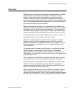
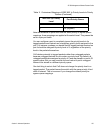
For example, when a tagged packet with a priority level of 3 enters a port
on the switch, the packet is stored in Q3 queue on the egress port.
Note that priority 0 is mapped to CoS queue 1 instead of CoS queue 0
because tagged traffic that has never been prioritized has a VLAN tag
User Priority of 0. If priority 0 was mapped to CoS queue 0, this default
traffic goes to the lowest queue, which is probably undesirable. This
mapping also makes it possible to give some traffic a lower priority than
the default traffic.
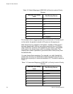
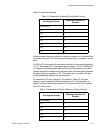
You can change these mappings. For example, you might decide that
packets with a priority of 5 should be handled by egress queue Q3 and
packets with a priority of 2 should be handled in Q1. The result is shown in
Table 11.
Table 10. Default Mappings of IEEE 802.1p Priority Levels to Priority
Queues
IEEE 802.1p Priority
Level
Port Priority Queue
0 Q1
1 Q0 (lowest)
2Q2
3Q3
4Q4
5Q5
6Q6
7 Q7 (highest)
Table 11. Customized Mappings of IEEE 802.1p Priority Levels to Priority
Queues
IEEE 802.1p Priority
Level
Port Priority Queue
0 Q1
1 Q0 (lowest)
2Q1
3Q3
4Q4
5Q3