


Chapter 24: Multiple VLAN Modes
276 Section VI: Virtual LANs
802.1Q- Compliant Multiple VLAN Mode
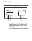
In this mode, each port is placed into a separate VLAN as an untagged
port. The VLAN names and VID numbers are based on the port numbers.
For example, the VLAN for port 4 is named Client_VLAN_4 and is given
the VID of 4, the VLAN for port 5 is named Client_VLAN_5 and has a VID
of 5, and so on.
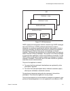
The VLAN configuration is accomplished automatically by the switch. After
you select the mode and an uplink port, the switch forms the VLANs. It
also assigns the PVID values as well. For example, the PVID for port 4 is
assigned as 4, to match the VID of 4.
A user-designated port on the switch functions as an uplink port, which
can be connected to a shared device such as a router for access to a
WAN. This port is placed as a tagged port in each VLAN. Thus, while the
switch ports are separated from each other in their individual VLANs, they
all have access to the uplink port.
The uplink port also has its own VLAN, where it is an untagged member.
This VLAN is called Uplink_VLAN.
Note
In 802.1Q Multiple VLAN mode, the device connected to the uplink
port must be IEEE 802.1Q-compliant.
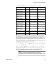
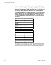
An example of the 802.1Q-compliant VLAN mode is shown in Table 20.
The table shows the VLANs on the AT-9400 Switch where port 22 has
been selected as the uplink port.
Table 20. 802.1Q-Compliant Multiple VLAN Example
VLAN Name VID Untagged Port Tagged Port
Client_VLAN_1 1 1 22
Client_VLAN_2 2 2 22
Client_VLAN_3 3 3 22
Client_VLAN_4 4 4 22
Client_VLAN_5 5 5 22
Client_VLAN_6 6 6 22
Client_VLAN_7 7 7 22
Client_VLAN_8 8 8 22
Client_VLAN_9 9 9 22