


724-746-5500 | blackbox.com
Page 18
Chapter 2: Overview
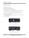
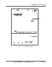
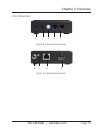
2.6.3 Indicators
The LEDs on the extender units show the real-time status indicating the linking and
communication between the Transmitter/Sender unit and the Receiver unit. Users
can identify the current status through the LED indicators on the unit.
The quality of the output signal will depend largely upon the quality of the video
source, cable, and display device used. Low-quality cables degrade output signals,
causing elevated noise levels. Use the proper cable and make sure the display device
can handle the resolution and refresh rate selected.
NOTE: The system will disable the video output signal when it detects non-HDCP-
compliant display(s) trying to play on the HDCP video source. All the
connected output displays MUST be HDCP compliant when the video source
is HDCP compliant.
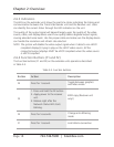
2.6.4 Function Buttons (F1 and F2)
The Function buttons (F1 and F2) on the extender units operate as described
in Table 2-3.
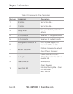
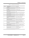
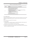
Table 2-3. Function buttons.
Button Action Description
F2 Press for 1 second.
Toggle between graphics
and video mode.
F2
1. Press and hold the F2 button.
2. Apply power to the receiver
unit.
3. Release right after the
Network Status LED starts
blinking.
EDID copy (Receiver unit
only!)
F2 Press for 5 seconds.
Change anti-dithering
mode
F1 Press for 1 second. Link/Unlink connection