


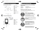
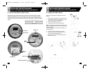
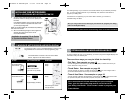
C . Install Your Meter Sensor
1. Wipe the meter dome clean with the
damp cloth.
2. Fit the Meter Sensor over your utility
meter as shown, so that the Sensor
Head sits as close as possible to the
front of the glass dome.
3. Tighten the clamp until the Meter
Sensor is snug, but can move just
enough to allow for slight adjustments.
4. Position the Sensor Arm as shown to
the right:
Note: The LED at the end of the
Sensor Arm must be positioned directly
over the optical port on the meter.
5 . Press the RESET bu tto n . The STAT U S
I n d i c a t or will light solid red while the
M e t er Sensor looks for a signal from the
m e t e r.
6 . When you have positioned the Sensor
Head corre c t l y, the red STATUS Indicato r
s t a r ts flashing re g u l a rly, indicating that the
Sensor has dete c ted the signal from yo u r
m e t e r. Within one minu te, in addition to the
regular fl a s h i n g , you should see an ex t r a
flash now and then, depending on your
ra t e of electri c i ty consumption.These
ex t r a flashes are normal, and indicate
that the Sensor is reading the mete r’s
o u t p u t correctly.
N OT E : To maximize batte ry life, the indicato r
s t ops flashing after about two minu t e s .
7. Tighten the clamp just enough so that the
Meter Sensor cannot move.
1312
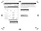
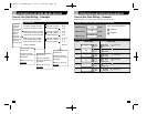
0 3 I N S TALLING YOUR METER SENSOR
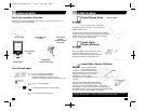
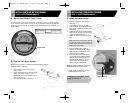
TYPE 2—ELECTRONIC WITH OPTICAL PORT ON FAC E
Status Light Indicator
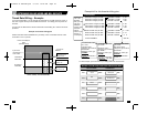
0 3 I N S TALLING YOUR METER SENSOR
TYPE 3—ELECTRONIC WITH OPTICAL PORT ON TO P
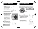
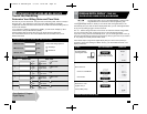
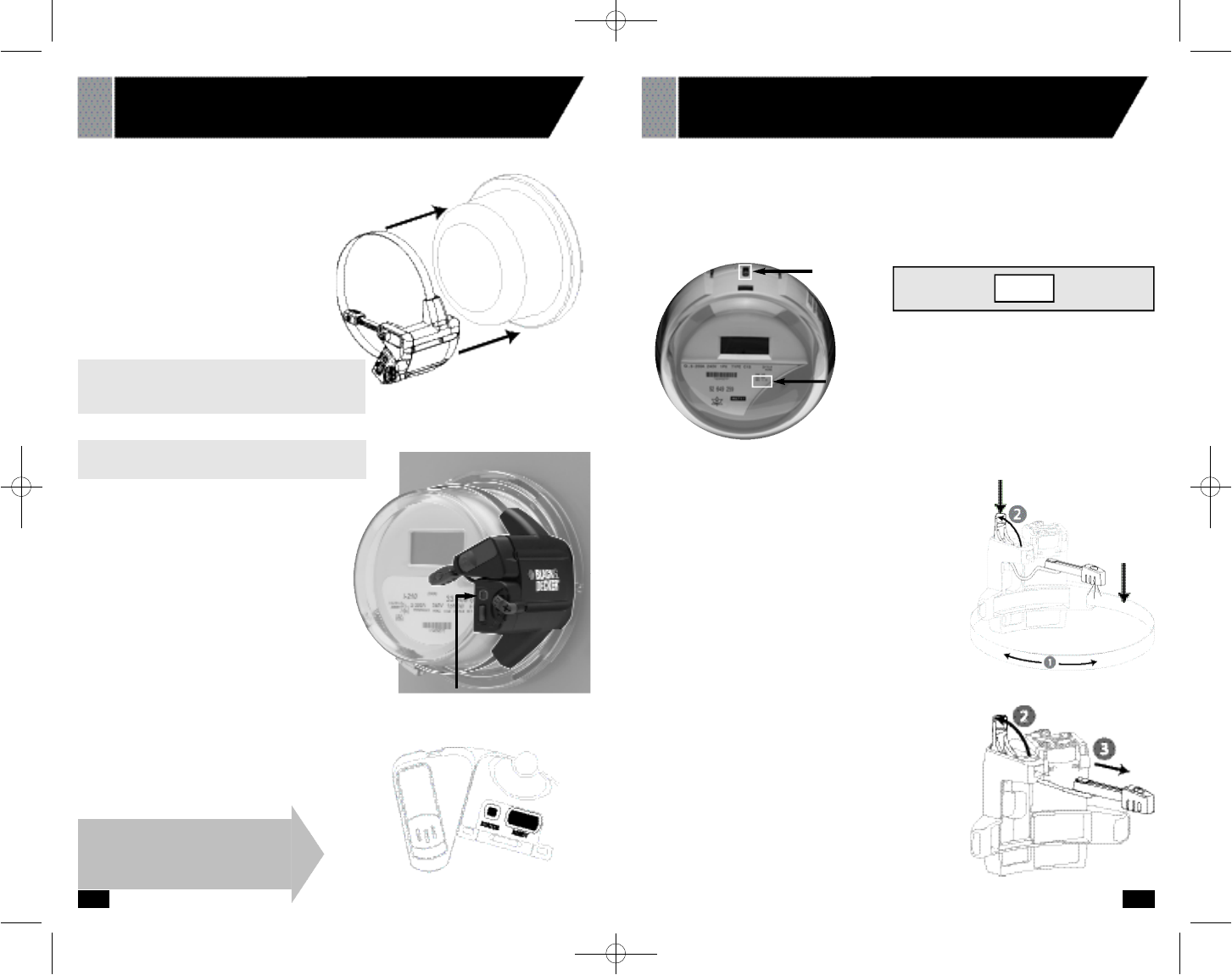
A . Record Your Meter’s Power F a c t o r
Find and re c o r d your mete r’s Power Fa c t o r. On the face of the mete r , look for a number
p receded by the lette r s Kh, Ks, or Kt.This number is usually 1.0 for an electronic mete r. If yo u r
m e ter lists more than one of these nu m b e rs, look for the smallest nu m b e r.Wri te this number in
the box below.You will need it later (in section 06) when you pro g ram your Digital Display.
Power Factor
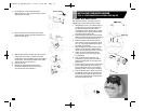
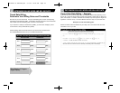
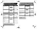
B . Prepare Your Meter Sensor
Make sure the batteries are installed in the Meter Sensor.
For this type of mete r, you need to re c o n f i g u r e the Sensor.
1. Use a flat-head screwd ri ver to open the clamping strap
all the way until it opens. Re m ove the strap from the
Sensor body.
2 . Pull the Sensor A rm Latch Cover up to unlock
the arm as shown (2).
3 . Pull the Sensor A rm complete ly out of the
body until it is complete l y detached, connecte d
o n l y by the wire (3). You may need to pull hard .
Optical
Port Power Factor = (usually 1.0 Kh)
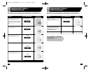
I n s t allation is complete! Go to
Section 4.
Note: If your electric meter has two optical
ports, align the sensor with the one on the left.
Latch Cover
Clamping
Strap
90539499 01 EM100B.qxd 7/7/08 10:05 AM Page 12