


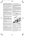
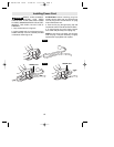
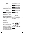
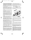

90° CUTTING ANGLE CHECK
Disconnect plug from power source. Set foot
to maximum depth of cut setting. Loosen
bevel adjustment lever, set to 0° on quadrant,
retighten bevel adjustment lever first, then the
depth adjustment lever and check for 90°
angle between the blade and bottom plane of
foot with a square (Fig. 4). Make adjustments
by turning the small alignment screw from
bottom side of foot, if necessary (Fig. 4).
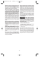
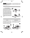
BEVEL ADJUSTMENT
Disconnect plug from power source. The
foot can be adjusted up to 45° by loosening
the bevel adjustment lever at the front of the
saw and aligning foot to desired angle on
calibrated quadrant. To maintain adjustment,
Always tighten bevel adjustment first, then
the depth adjustment lever (Fig. 5).
For 50° cuts, loosen bevel adjustment lever,
depress 45° stop spring, adjust foot to 50°
and tighten lever (Fig. 5). Because of the
increased amount of blade engagement in the
work and decreased stability of the foot, blade
binding may occur. Keep the saw steady and
the foot firmly on the workpiece.
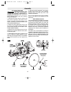
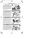
DEPTH ADJUSTMENT
Disconnect plug from power source. Loosen
the depth adjustment lever located between
the guard and handle of saw. Hold the foot
down with one hand and raise or lower saw
by the handle. Tighten lever at the depth
setting desired. Check desired depth (Fig. 3).
Not more than one tooth length of the blade
should extend below the material to be cut,
for minimum splintering (Fig. 3).
-10-
Operating Instructions
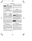
LINE GUIDE
For a straight 90° cut, use the large notch in
the foot. For 45° bevel cuts, use the small
notch (Fig. 6). The cutting guide notch will
give an approximate line of cut. Make sample
cuts in scrap lumber to verify actual line of
cut. This will be helpful because of the
number of different blade types and
thicknesses available. To ensure minimum
splintering on the good side of the material to
be cut, face the good side down.
BLADE
90°
FOOT
BEVEL
ADJUSTMENT
LEVER
QUADRANT
FIG. 4
0°
QUADRANT
BEVEL
ADJUSTMENT
LEVER
FIG. 5
45° STOP
SPRING
FIG. 6
FOOT
45° / 50° BEVEL CUTS
90° VERTICAL CUTS
PUSH
45°STOP
SPRING IN
DIRECTION
OF ARROW
FOR 50°
BEVEL
ADJUSTMENT
FIG. 3
DEPTH ADJUSTMENT
LEVER
ONE TOOTH LENGTH SHOULD
PENETRATE WOOD FOR
MINIMUM SPLINTERING
ALIGNMENT
SCREW
BM 2610917132 10-03 10/28/03 11:07 AM Page 10