


36
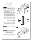
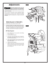
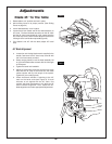
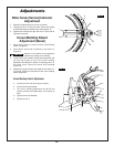
Blade 45° To The Table
1. Rotate table 1 to 0° position and lock in place.
2. Move sliding fence to its proper position. (See Sliding
Fence on page 54.)
3. Lower head assembly. Lock in place.
4. Loosen bevel lock handle and tilt the head assembly to
45° bevel. The bevel indicator should be on the 45° mark
and the 45° bevel stop should be in full contact with the
45° bevel stop screw, and the blade 2 should contact the
full length of the combination square 3 (Figure 8).
5. If the blade is not 45° with the table, adjust 45° bevel
stop.
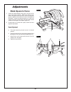
45° Blade Alignment
a. Loosen jam nut 4 using blade wrench supplied in the
handle, and lower the 45° bevel stop screw 5 with
the 3 mm hex wrench provided.
b. Grasp carrying handle, move the head assembly left
or right until blade makes contact with the full length
of the square.
c. Tighten the bevel lock handle 6.
d. Adjust 45° bevel stop screw 5 so that the hex screw
head hits the 45° stop at the same time the blade
makes contact with the full length of the square.
Tighten 45° jam nut 4 (Figure 9).
e. Check that bevel indicator is pointing to the 45°
mark on the bevel scale (see Figure 8). If bevel
indicator is not aligned with the 45° mark, first
recheck the blade squareness to the table and 0°
bevel indicator alignment. Then, repeat the 45°
blade alignment and make appropriate adjustments.
Adjustments
FIG. 8
1
3
2
FIG. 9
6
4
5