


42
Adjustments
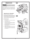
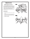
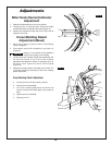
Miter Scale (Vernier) Indicator
Adjustment
1. Raise the head assembly to the full-up position.
2. Through the slot 1 in the kerf insert, loosen the Phillips
screw 2 that holds the indicator 3 in place (Figure 12).
3. Position the indicator 3 to align with the 0° miter mark 4.
Tighten the screw 2.
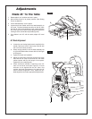
Crown Molding Detent
Adjustment (Bevel)
1. Move sliding fence to proper position. (See Sliding
Fence on page 54.)
2. Push detent stop pin 5 completely in as shown in
(Figure13).
Keep pin in out position for all operations
except when cutting crown molding.
3. Loosen bevel lock handle 6. Rotate head assembly until
the stop pin 5 rests on top of the crown molding
adjustment bolt 8 and the pointer is indicating 33.9° on
the bevel scale. Tighten the bevel lock handle 6
(Figure 13).
4. Measure the angle between the blade and the table. If it
is not 33.9° follow the procedures for the crown molding
detent adjustment.
Crown Molding Detent Adjustment
a. Loosen jam nut 7 with the wrench provided.
b. Loosen bevel lock handle 6.
c. Turn crown molding adjustment bolt 8 with the
wrench provided until blade aligns a the square at
33.9°.
d. Tighten bevel lock handle 6.
e Tighten jam nut 7.
40
35
30
25
20
15
10
5
0
5
10
15
20
25
316
225
30
35
40
45
FIG. 12
FIG. 13
2
4
3
1
6
5
7
8
CAUTION
!