


22.
If you are making a rip type cut in thinner materials, the auxuiliary
facing should be attached to the fence so that the bottom edge
touches the top surface of the table. In this situation, the facing
must be lower than the fence. This will prevent thin material from
sliding under the rip fence.
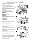
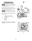
19. BLADE GUARD
Protects the operator, and must always be in place and working
properly for all thru-sawing cuts. That is all cuts whereby the blade
cuts completely through the workpiece.
To remove the guard for special operation, loosen socket head
screw with the wrench provided and remove blade guard and
spreader. DO NOT DISTURB THE SETTING OF THE SPREADER
SUPPORT BRACKET. When replacing guard, Make sure spreader
is between the support bracket and the clamping plate. TIGHTEN
SOCKET HEAD SCREW SECURELY (See page 32).
20. TABLE INSERT
Is removable for removing or installing blade or other cutting tools.
For your own safety, turn switch “OFF” and
remove plug from power source before removing
insert.
To remove the insert:
A. Raise the blade above the table surface.
B. Raise blade guard.
C. Using a screwdriver in slot at front of insert, lift from pocket in
table.
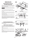
Adjusting the table insert
The table insert should be adjusted so it is flush with the saw table
surface.
A. Place a straight edge or square on the saw table extending over
the insert.
B. If adjustment is necessary, adjust the insert flush with the table
by turning four leveling screws
Never operate the saw without the proper insert in place. Use the
saw insert when sawing; the dado insert when dadoing; and the
molding insert when making molding cuts.
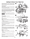
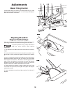
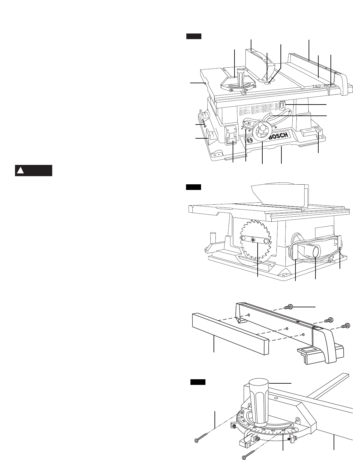
21. MITER GAUGE
Head can be locked in desired position for crosscutting or mitering
by tightening the lock knob. ALWAYS SECURELY LOCK IT WHEN
IN USE.
A template for drilling holes in the miter gauge 21 is provided on
page 63, which allows you to attach an AUXILIARY FACING 23 to
provide additional support to cut longer pieces. Select a suitable
piece of smooth straight wood, drill two holes through it and
attach it with screws 24 (Fig. 3).
Example:
A. Drill 1/4" dia. holes thru miter gauge.
B. Drill 5/32" dia. holes thru (board 3/4" thick, 3" high, and desired
length).
C. Attach with two No. 12 round head screws 1-1/2" long, 24, not
included (Fig. 3).
Be sure screws never protrude above outside surface of facing.
Be sure facing does not interfere with the proper operation of the
saw blade guard.
NOTE: When bevel crosscutting, attach facing so that it extends
to the right of the miter gauge and use the miter gauge in the
groove to the right of the blade.
Getting To Know Your Table Saw
WARNING
!
13
3
7
1
4
11
8
19
2
21
18
20
FIG. 1
FIG. 2
14
16
17
9
16
6
12
5
15
10
23
22
24
25
24
FIG. 3