


-27-
(0F$?4A0C8>=B
"8C4ADC
•
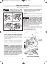
A “miter cut” is a cross-cut made with the blade vertical
(non-tilted) at a horizontal angle relative to the fence.
• A miter cut is made at 0° bevel and any miter angle
in the range from 52° left to 60° right.
• The miter scale shows the angle of the blade
relative to the fence angle is cast-in on the table for
easy reading.
• Positive detents have been provided for fast and
accurate mitering at 0°, 15°, 22.5°, 31.6°
and 45° left and right and 60° right.
• The crown molding detents (left and right) are at
31.6° (See Cutting Crown Molding for more infor-
mation page 32).
• For precision settings at angles next to the
detents, use the detent override to lock out the
detent. This prevents the wedge on the detent
lever from slipping back into the detent.
• A miter cut can be made as either a chop cut or a
slide cut, depending on the width of the workpiece.
• The kerf inserts should be as close to the blade as
possible without touching the blade (see Kerf In-
serts for adjustment procedures).
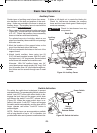
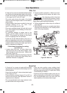
>;;>FC74B48=BCAD2C8>=B5>A<0:8=6
H>DA<8C4A2DC
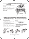
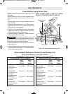
1. Loosen miter lock knob. Lift miter detent lever
and move the saw to the desired angle, using
either the detents or the miter scale. Tighten miter
lock knob (Figure 32).
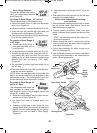
2. Extend the base extensions and fence on the side
on which the cut will be made. (See Sliding Fence
and Base Extension on page 25).
3. Properly position workpiece. Make sure work-
piece is clamped firmly against the table or the
fence.
Use clamping position that does
not interfere with operation. Before
switching on, lower head assembly to make sure
clamp clears guard and head assembly.
4. Follow procedures for either chop cut or slide cut
(see page 26).
5. Wait until blade comes to a complete stop before
returning head assembly to the raised position
and/or removing workpiece.
,>A:?8424
"8C4A!>2:
=>1
"8C4A
(20;4
4C4=CB
&D82:
2C8>=
;0<?
!
WARNING
86DA4"8C4ADC
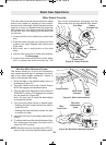
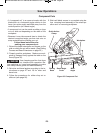
4E4;DC
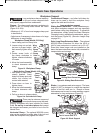
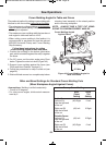
KA “bevel cut” is a cross-cut made with the blade
perpendicular to the fence but tilted away from the
vertical position.
KA bevel cut is made at 0° miter and any bevel angle
in the range up to 47°.
KThere are factory set bevel stops at 0° and 45° on
both the left and right. (See Adjustment section if
adjustments are required.)
KThe front-positioned bevel range selector knob
provides three bevel range choices.
K There are also positive crown molding bevel
stops at 33.9° on both the left and right. Disengage
this stop unless using the 33.9° angle (See Cutting
Crown Molding for details.)
K A bevel cut can be made as either a chop cut or a
slide cut depending on the width of the workpiece.
K The front-positioned bevel lock lever locks the
head assembly at the desired bevel angle.
BM 2610012089 03-10 E:BM 2610012089 03-10 E 3/30/10 7:41 AM Page 27